Quantcast
Channel: 3D printer improvements

How to use Openscad, tricks and tips to design a parametric 3D object

$
0
0

Part 1/3: Introduction to constructive solid geometry with Openscad

Some technical and non-technical people keep asking me how I create new designs. As often, after a few personal replies, I end up heading to the blog to share the answer as they keep asking for more.

Also I long wanted to write a pragmatic and step-by-step introduction to Openscad. The idea is to help people even with no programming skills (mostly in this part) and to bring newcomers to a point that they can design their own 3D objects (part two).
If only a few readers switch to "designers" by reading this I will be quite happy. Meanwhile I will have given a detailed answer to my friends and contacts!

A non-obvious GoPro mount that is fully customizable thanks to Openscad.
It looks complex, but it is still exclusively made of spheres, cylinders and cubes with a few basic "joints".
A forthcoming last part will deal with the complex features of Openscad. This one is for people that either learn fast or for those that are already proficient with the usual features of Openscad.

So first, what is Openscad? Within the CAD family, it is a 3D modeler: a software that helps you to create 3D objects. There are many such tools, but this one is used extensively in the 3D printing community, not only because it is free but because is it really efficient for some kind of objects.

It may or may not suit your mind, but with time I am able to "see" the shape I describe, not as text but directly as shapes. I guess it depends on people, but I am sure there are people that are not programmers that can think alike. And if you are already a programmer with no industrial goal then you really should give it a try. It will be a breeze to use up to a productive level, especially if you do not want to invest time in a new and hellish interactive user interface!

The official manual is OK but it does not really work as an introduction. The navigation is also sometimes difficult to the point goggle is more useful. There is a nice raw cheat sheet also but it has no link to the respective functions (what a pity!). In any case these fail to help learning Openscad quickly in my humble opinion.


Why Openscad?

The software shines whenever you want:

1) precise placement of object (as all objects have explicit numbered coordinates and sizes)

2) easily modifiable design, e.g. when you want to make a wall thicker or a hole larger, and the whole design adapts to the new numbers automatically. It is thus easy to find the "optimum" geometry, weight or robustness for real life applications.

3) a text-readable design, and easily recyclable components or behaviors


It is no surprise that Openscad is best suited to mechanical designs. As we said, compared to other 3D modelers, it shines when a number of iterations are required before the optimum geometry is obtained, because everything is controlled by numbers that can be tweaked extremely easily and at will (when it is programmed correctly).

Now reciprocally, Openscad fails badly with organic shapes though: it is not the right tool to design a mascot, statue, or non-abstract art. My only attempt at art was the arguable bird-o-matic generator, which create simplified bird shapes with a few geometric shapes ;)

An attempt to generate bird shapes from one single design
Openscad usually not a good tool for artists.


Introduction


Openscad is still programmed. Designs are described withing a text file, that it parses to generate and show 3D shapes. The mouse is only useful to view, zoom and rotate around the generated shape.

But do not be afraid if you are not a programmer as you still can do a lot by following very intuitive rules.

CSG and incremental design


The basic ideas of constructive solid geometry is not unlike the process an artist follows when he works with clay: he starts with nothing, and then he adds or removes material to make a shape that becomes closer and closer to his final idea. Parts of the object can also be made separately, like hands or arms for a statue that are stuck to the trunk once finalized.

Openscad and CSG in general works the exact same way, except that each of the step is described with names and explicit commands, that are applied one after another. "Carving" is even easier than in real life because any shape can be removed (including complex ones that are themselves built by adding elements!).

Encoding of a 3D object


You can bypass this section when you do not care or if you get  feel lost, but it may help understand better.

A 3D sphere! Actually it is a mesh of triangles
that approximates what we think is a perfect sphere.
Virtual 3D designs are fed to printers through a slicer, which computes the many commands to move the printer motors and temperatures. The most common file format to give to a slicer is STL, which is a primitive but powerful way to encode a 3D geometrical shape.

But... it is only an approximation of the 3D object, wit a mesh of 3D triangles, also called a wireframe.

The STL file can even be opened with a text editor to show that it is a dumb list of triangles, that themselves rely of a set of points (known as 3D vertices). In fact, STL files can easily be generated by homemade programs to create mathematical shapes.

Note: newer formats are slowly emerging, like the AMF, (appropriately named "Additive Manufacturing File Format"). Indeed, STL only stores really basic information, while more and more is expected: curved surfaces, material, densities, heads, settings and so. In some time Voxels formats may raise, especially well suited to local material and properties. But for now they have their own set of serious problems (mostly memory requirements).

How to edit an openscad file: huh, forget the embedded editor!


In my opinion the editor that comes bundled with Openscad is not only a real failure but also a waste of resources... I wish the authors spend more time on Openscad 3D and not on an editor! Now it is free so it is difficult to complain! But if at least it had "point and click" links between the 3D preview and the editor like the promising and gorgeous coffescad... But no, it even did not have any "Search" feature for years and only recently introduced colored keywords!

So I highly recommend you use a regular text editor instead (notepad++, ultraedit, kate, gnome-editor... just avoid the stinking default windows notepad, which is as useful as an ashtray on a motorbike). Then, you will like to hide and forget the embedded editor (tick "menu "View / Hide editor" in the Openscad menu).

A text editor with syntax coloring for Openscad (kate / Kubuntu / Linux)
There are also extensions to color the language keywords according to the Openscad syntax. If you do not get them from this page, you may find them with Google with your editor name and "syntax coloring openscad".

Now when editing the design, you would have to press F5 to refresh the view when the source changes.
I recommend you tick instead the "Automatic Reload And Compile" option in the "Design" menu, so that Openscad refreshes the view as soon as you save your work. Only when the design is incredibly complex it makes sense not to refresh each time. But in this case it is better to "deactivate" part of the design when you work on some other (we'll see this in "debugging" below).

Also, when you are done, you will need to export your file in the STL format, for the slicer to process it and to generate the gcode commands to print the object. To do so, just press "F6" and Openscad computes the shape thoroughly, then "Export as STL..." (in the newest version of Openscad, this is in the "File" menu, while former versions had it in the "Design" menu).

Now, be aware that your source code extension is ".scad". Do not confuse with the the generated STL file! Scad files describe the shape in the Openscad language, while STL files are raw geometric triangular meshes. There is no way to restore a scad file from an STL, so make sure to save your scad design files (they are more important than the STL files).

Basic language items


Openscad language mostly looks like the C computing language, or even Java, Javascript or... well many of the modern languages. But keep reading please, because it is also way simpler both to write and to debug!

Of course typos are still forbidden, as they generate dreaded "syntax errors". When Openscad does not understand what you are trying to tell him (i.e. it seems not to react to your change), you should check the "console" of Openscad (disable the tick mark in the "View / Hide Console" menu). This is where you read the erroneous line number. Then go back to your editor and fix the error!

Each command you give to Openscad must end with a semicolon. This is to tell Openscad that it has to do something at this point, while the former elements are preparing the work to do, like positioning the item or applying a transformation, and eventually telling the shape:

  sphere(20);

As you can see, the parameters are given in a pair of parentheses. Here we tell that the "sphere" has a radius of 20. Units are all millimeters, so if you want a huge and out of bounds 20 inch ball, just multiply the value:

  sphere(20 * 25.4); // as 1 inch is 25.4 millimeters

See also above? I wrote a comment in the source. Easy: Openscad ignores all text which is past a tight pair of slash characters until the end of the line. So this is where you put reminders, todos or any kind of useful information, mostly to be able to read the source months later! I highly recommend you put comments at every place that you may stumble upon later and ask "what the heck did I do here?".

Of course you can add, subtract, multiply or divide numbers. But there are a small set of usual mathematical functions like abs(x) for the absolute value of the number x, cosines and so. Usually there is no need to check the list if you ever programmed once.

Enough for the theory, as it will be made easier with examples.

Basic shapes and language items


The "primitive" shapes in Openscad are surprisingly few: spheres, cylinders and cubes. Period.

Everything is made with these shapes, including the very complex one below (OK, with the help of a few smart operations that I will explain later).

The rollerstruder, a filament driver for 3D printers.
Still made only of cubes, spheres and cylinders, but 1000+ lines of Openscad!


The primitive sphere, and how to view your shape


Let's start with the minimal or so-called primitive shapes. These are the basic building blocks, not unlike lego bricks except that there are fewer of them, and that we are going to distort them a lot later!

Just write the following in a file named "temp.scad", which you open with Openscad. Use F5 to refresh the view after you save the file, unless you have configured it for an automatic refresh (see above).

  sphere(20);

It will create and show a sphere that has a radius of 20 mm (i.e. a diameter of 40 mm). As shown, the sphere is centered on the three X,Y,Z axes by default.

A dumb sphere of radius 20 mm.
You can move around the object with:
 - left click + drag to rotate the view
 - right click + drag to translate the view
Additionally you can zoom with the mouse wheel (or shift + right click + drag).
None of these will change the shape nor its position in space: only your point of view will vary.
If you get lost, you can restore "easy" point of views with the well-named "View" menu.

The origin is shown as the intersection of the main long line segments of course, buried in the sphere above. But check the tiny (X,Y,Z) axes at the bottom left of the screen: they really helps when you start to translate objects for example, as the design becomes more complex.

Back to the sphere...

  sphere(20);

Now, and contrary to many languages, Openscad lets you name explicitly the parameters. I highly recommend this usage. Here you would re-write the above statement this way:

  sphere(r=20);

In the above, "r" is called a "parameter". Naming parameters makes it more readable and less prone to errors (well, especially when there are more than one value to give). In fact named parameters usually become compulsory at some time.


Another primitive shape: the cylinder


To create a cylinder, just clear your source and type this instead:

  cylinder(r=10, h=20);

You see now why naming parameters are useful? Without them it would become more difficult to know which is the radius and which is the height. And with names, the order of the properties no more counts:

  cylinder(h=20, r=10);

Default cylinder placement: flat on the (X,Y) plane.

Actually you could omit "h", and it will revert to the default value of 1 mm. Hence, to create a 20 mm wide and 1 mm thick "coin", you could write only this:

  cylinder(r=10);

Of course, it not recommended as we usually never omit "r" nor "h" for a cylinder.

But there are other parameters that are often left out, like this one:
  cylinder(h=20, r=10, center=true);

Explicitly "centered" cylinder: it is now halfway into the (X,Y) plane.

The latter tells Openscad to "center" the shape vertically: it is now half through the floor, whereas it was flat on it when "center" before (because the default value for "center" is false!).

Hence any of the two following commands create/define the exact same cylinder. However it is not a good practice to randomize the order of your parameters as it makes the source harder to read! Better stick to one convention only:

  cylinder(r=10, h=20);
  cylinder(h=20center=false, r=10); // same stuff


As we have seen with the scad-to-STL process, the cylinder really is approximated with spatial triangles, not curves. Remember: all boils down to triangular meshes at the end!

Given the size of the cylinder, Openscad tries to guess how many facets it shall use to get a correct approximation of the "ideal" cylinder. But sometimes you want either more for a finer surface, or you want a specific number of facets.

This happens when you want to model hexagonal nuts for example: they are just cylinders with 6 facets after all!

  cylinder(r=10, h=20, $fn=6);

The special "$fn" variable sets the number of facets that are generated to create the shape. You should not use it if your goal is to generate finer details though (we'll see that below).

Specifying the number of facets of a cylinder for a hexagonal shape with the $fn variable.

Of course with 4 facets you would get a tower that actually is a "cube", but there is a specific primitive for this.

Interlude: a technical note about the precision of the facets


You can skip this paragraph unless you feel comfortable or interested by the underlying triangular 3D mesh. As we have seen all the shapes are composed of triangles at the lower level.

We see these facets in Openscad, even without asking for it explicitly. But by choosing "View / Wireframe", you can see that even flat rectangular facets are subdiveded into triangles!

Now, when you want to get a finer surface, please do not use "$fn" as many people tend to do. Its purpose is to set the number of facets in very specific cases as above (the hexagonal nut), and not really to define the geometric resolution.

Indeed, the right "number" of facets depends on the size of the object, which is hard to tell when it gets scaled or buried in other larger shapes. For example, asking for 100 facets on a 1 mm wide cylinder is nonsense. It would slow your computer quite a bit, and even more for more complex shapes.

To set the resolution of the mesh (smoothness of do so neatly, there are two specialized variables: $fa and $fs to do so. They respectively define the "minimum angle" and "minimum size" of the facets. The minimum angle tells Openscad to break a facet in two when the angle it has with its neighbors goes above a certain level. The minimum size makes Openscad subdivide the facet when it becomes too large.

So when you want to get smoother surface, you can use values of 0.5 for $fa and 0.5 for $fs for example, this way:

  cylinder(r=3, h=10, $fa=0.5, $fs=0.5);

Zooming the view on the cylinder will now show that it got smoother (technically "approximated with many more facets").
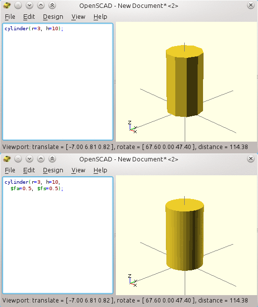
Two mesh precision, animated, defined by the $fa and $fs special properties.
See also how you can use spaces and newlines just to better format the source!

If you want to achieve the same resolution for each and every primitive shape in your design, it is easier to set them as the default values, like this:

  $fa=0.5; // default minimum facet angle is now 0.5
  $fs=0.5; // default minimum facet size is now 0.5 mm
  cylinder(r=3,h=10);

The deal is these values are used unless a primitive has his own explicit values (as they get the priority of course). And unless $fn is explicitly given, it is computed according to the $fa and $fs values. Here we are.

Another useful strategy is to use $fa=1 and $fs=1.5 as long as you are in the design phase, building your shapes. This gives you a fast and reactive rendering. Only once you are done, you cen set them to smaller values, so as to save/export a very smooth STL mesh (i.e. once the design is done). It will grow larger as a file also (no need to have 80MB STL files for a 3D printer, as it cannot be so precise!).


The cube, and [X,Y,Z] vectors in Openscad


Mathematically speaking, these are cuboids (non symmetric cubes), but that's how Openscad names them.
Anyhow, they use a special notation or "syntax": instead of explicit naming, you must provide the 3 sizes along the X, Y, and Z axes respectively, and this way :

  cube([20,10,5]);

See the three-numbers-in-brackets? They define a 3-element "vector", where the components sets the dimensions of the cube on the X, Y and Z directions respectively.

Do not forget the square brackets or Openscad will yell at you in the "console" windows (once again it is almost necessary to leave it open -- not shown on the screenshots here though!).

Cube (default placement is towards the positive X,Y,Z directions)
So we have created here a cube that is 40 mm along the X axis, 10 mm on Y and 5 mm high.

One problem with cubes is they are either in the positive quadrant (X,Y,Z) as above, or they are fully centered on the origin of the axes when the "center" parameter is true like below:
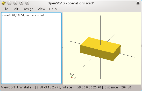
Cube (centered on all three axes)
We are going to see how to "fix" this now.

Basic operations: where it all starts!


First of all, let us translate some cube (i.e. shift the position of the object)


As we have seen, there is no way to lay a cube like cylinders, i.e. centered on X,Y where the bottom is kept at position Z=0. But Openscad, as any CSG modeler, has a set of basic geometrical transformations.

And the easiest one is the translation which is exactly what we need here. But contrary to the primitive shapes, a translation does not define an object. Instead, it modifies the object that follows!

Like the cube, translations expects a vector of 3 values, one per axis.

We can now translate our cube, with the following syntax:

  translate([0,0,2.5]) cube([20,10,5],center=true);

It does not matter how much space or new lines you put in between the two, or after of before the commas and other symbols. But you should write the semicolon only at the end, after you are done telling that something really is done, and "translate" expects a shape!

Once again, translations as all the other non-primitive operations do not do anything by themselves, they just "modify" shapes that comes after them.

We raised the previously centered cube flat on the (X,Y) plane,
thanks to a translation of half its size toward positive Z.

What it does is to leave the cube at the same X and Y positions (zero offset on X and on Y), but it moves the cube up by 2.5 mm on Z (of course, negative numbers would sink the cube towards the bottom).

In our case, the cube was 5 mm tall, and positioned halfway on the (X,Y) plane. This is why we are raising it by 2.5 mm, i.e. half of its height: the result is a cube centered only on X and Y, and which is now flat on the (X,Y) plane at Z=0.

Just like default cylinders are laid out!


Union of shapes: where "constructive solid geometry" start to make sense!


Now for a new and important operation! So called "unions" are also the default behavior in Openscad when you write more than one shape. What happens is that they get added/merged together.

So when you write:
  cube([20,20,20], center=true);
  sphere(14);

Then Openscad creates a new shape which surface really becomes a mix of a cube and a sphere, as shown below!


Union (addition) of a cube and a slightly larger sphere in Openscad.
The union( ) operator is implicit. The result really is a mix of both.

Oh, by the way: to make it clearer, you can give a color to one of the shapes, by specifying a vector of three R,G,B values (they are numbers within 0 and 1, and not 255 as usual):

Using colors to understand what happens!
Actually, you will get the exact same behavior with this slightly more verbose way. Writing explicit "unions( )" operators really are useful, as we will see in a short moment.

  union()
  {
    cube([20,20,20], center=true);
    sphere(14);
  }

This creates a new (non-primitive) shape by fusing the primitives that are given within the curly braces, merging them into each other.

The above syntax is new however. Easy! You can consider curly braces { like this } to be nothing more than a way to group shapes, so that a former operator like our "union( )" is applied to the whole group.

We use curly braces in many cases: for example, to translate the two object by 10 mm further on the Y axis and 3 mm downwards on the Z, we would use this syntax:

  translate([0,10,-3])
  {
    cube([20,20,20], center=true);
    sphere(14);
  }

Of course you are not limited to two shapes: you can add as many as you want.

Make sure to understand the importance of these curly braces, because only the cube would be shifted if written like this:

  translate([0,10,-3])
    cube([20,20,20], center=true);
    sphere(14);

Remember, spaces are only conventions to make it more readable, and an operator only applies to the next "block". Indentation is just a convention. So if you are unsure, you can always add curly braces after such an operator, even if there is only one object that gets translated.

So curly braces are just a way to group a bunch of shapes that are modified altogether.


Now for some real difference...


As much as you can add one primitive to another, you can also subtract one shape from another, effectively carving the first shape by means of the second shape.

The "difference( )" operator also applies on a number of shapes, just as the union above. Now the order is important though, because it create the first shape as usual (positive shape), and then it subtract the shape of every other subsequent item (negative shapes), i.e. removing material each time.

Consider this example:

  difference()
  {
    cube([20,20,20], center=true);
    sphere(14);
  }
Difference (subtraction) of a cube and a slightly larger sphere in Openscad
Do you see how the sphere became a "negative shape"?
The first shape is "solid", and all subsequent shapes remove material from it.


The danger of CSG subtraction: dreaded undefined surfaces!


There is an extremely important thing to know though here. When you subtract a shape from another one, you must make sure not to leave any wall or surface with no thickness. Seriously, this happens often if you do not take care of it.

Say e.g. you want a cube with a cylindrical hole through it. The naive idea then is to create a cube, and then subtract a cylinder from it. And it can be done like this, true?

  difference()
  {
    cube([20,20,20]); // a 20 mm cube
    translate([10,10,0]) // move origin
      cylinder(r=5,h=20);
  }
Terribly wrong! This definition leaves the top hole surface undefined:
hey, is it within or outside of the object? This surface has no thickness!
But this is wrong! Really! Think about the poor computer: at the cylinder outer limits you created surfaces with no thickness at all. The result is said to be "non manifold".

Such wrong surfaces cannot be parsed correctly by 3D printer slicers: shall they really create an infinitely thin surface there or just drop it? Contrary to most serious CAD tools, the so intuitive Sketchup is very broken in this regard, as it leaves a lot of undefined surfaces while the user design them interactively (in turn, it explains why so many Sketchup designs are so hard to slice and to 3D print -- and why I just cannot recommend this CAD software... at least check regularly with a 3D slicer to know when your design broke!).

More annoying even, such undefined surfaces are very hard to find and fix afterwards.

So what should we do?

The only safe solution is always to carve a bit more than what you want intuitively!
So, making the cylinder one more millimeter taller lets it protrude out of the cube, right?

  difference()
  {
    cube([20,20,20]); // a 20 mm cube
    translate([10,10,0])
      cylinder(r=5,h=20+1); // higher
  }


No, wrong again! Do not forget that the same issue exists at the base of the cylinder also (Z=0), it is left neither in or out of the resulting shape.

The only real solution is to make sure the cylinder protrudes from both sides:

  difference()
  {
    cube([20,20,20]); // a 20 mm cube
    translate([10,10,-1]) // start 1 mm below the surface
      cylinder(r=5,h=20+1+1); // and go 1 mm above
  }

In this last fix, the cylinder really starts one millimeter below the (X,Y) plane, and stops one millimeter above the top of the cube.

The right way to subtract a shape in CSG: the shape to remove must
not leave undefined surface, so it must protrude a bit from the shape to carve.

Debugging a designs, looking for non-manifold issues


Openscad offers nice ways to double check design problems. Especially, subtracted objects are hard to see (obviously!), so they cause a lot of headaches at first.

But you may prefix any command or block with a dash character, and Openscad displays it as semi-transparent:

  difference()
  {
    cube([20,20,20]);
    translate([10,10,-1])
      #cylinder(r=5,h=20+2); // made half transparent to check!
  }
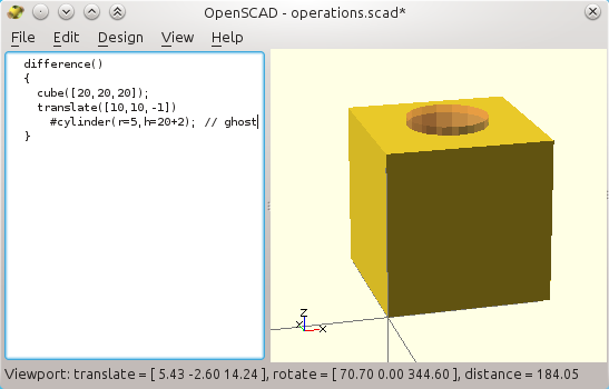
Using a dash to double check that the cylinder to subtract protrudes from the cube
on both sides. When rendered (F6), it will still be removed from the shape.

And other such "special" characters provide different ways to help debugging the design.

A propeller design from the official website, where the enclosure is a "ghost" just to provide a context.
Only the propeller will make it to the STL when exported to STL.
When a shape is prefixed with a star "*", Openscad will completely bypass it. It will not be shown, nor computed, not even appear in the "compiled" final shape (F6). This is useful when you are building a complex design and do not want to be distracted by parts that are not related to the one that is being built, either for better viewing or because they slow down the rendering.

Reciprocally, an exclamation mark "!" prefix only shows the given part (it hides all the others parts of the design). I use it all the time when I want to work on a sub-part of a complex design, without any disturbance from the remaining.

Disabling perspective is useful
to check alignment (bottom)
As shown in the complex shape above, the percent sign "%" is also very useful. It shows the shape as half transparent like the dash, but, in addition, the part will not be included in the final shape (F6, STL). This is very useful to draw bearings or other hardware components, or spaces that shall not be crossed in a design, and without impacting the final object. I call these "ghosts". And they also often embellish the rendering!


We already talked about the "color( )" operator, that just changes the color of a shape to make it stand out, with no other sort of impact on the final design.


Also in the view menu, you can show/hide the underlying triangular mesh, which is not that useful in my opinion.


But the menu also lets you disable the perspective. I often leave it in orthogonal mode, because it is easier to see whether parts are correctly aligned or not, and also to get a better sense of gaps between parts.

And well, being pretty does not mean being more efficient ;)


Rotation: a necessary evil


Using once again a three number vector, you can specify a rotation as well, on each X,Y,Z axis.

In practice we very rarely give more than one value to the "rotate( )" operator because it makes things immediately hard to follow! It is usually better to write two consecutive rotations than a combined one.

Here is an example:

  rotate([90,0,0])
  {
    cylinder(r=2, h=10);
  }

It first rotates the axis system by 90° anticlockwise around the X axis (the trigonometric way), and only then it creates a thin cylinder. The result is the following:

Rotated cylinder, by 90° anticlockwise around the X axis.
I tend to get the direction wrong all the time!
Easy so far, right?

But things tend to get more complicated if you rotate a complex shape and then try to work within the shape... The axes are no more oriented as the small X,Y,Z triplet in the bottom left of the view, so it is easy to get lost and translate shapes on the wrong direction.

In the fallen cylinder above, the Z axis is now an inverted version of the Y axis.


The best thing to do is
1) to practice a lot and flex your mind in a virtual 3D space (it does work after a while), or
2) simpler, use the "!" prefix on the block you are editing and after the "rotate( )". You then are back in an upright coordinate system! Once done, just remove the exclamation mark.
Using the "!" prefix is really useful to work in upright coordinates.
Rotated shapes makes life harder as axes no more match that of the main view.
See also how we had to use a union to "group" the two shapes?

Designing more complex shapes


We have seen the difference of two objects, but you can also have an intersection:

Intersection of two objects. The order no more imports.
Thanks to the curly braces, we know how to design more complex shapes. Remember, there could be one, two or any number of shapes within the curly braces, including non-primitive shapes!

For example, we create a simple mug by "carving" a vertical hole right in the middle of the former shape. We need a proper vertical offset to keep some material at the bottom (BTW, remember to let the hole protrude from the top, right? Use a dash or a percent prefix to double check if in doubt).
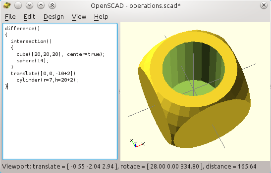
A simple mug with a slightly more comple shape.

The above shows how we usually work with CSG: build and refine shape after shape, making it more complex each time. It requires a bit of practice and people are not equal in this regard. But it is pretty efficient and not far from what many artists already do, and not different from a programmer's job either!

Note also that you can "get back" to the former shape simply by prefixing the "intersection( )" with an exclamation mark. Only this block will then be displayed and the effect of the "difference( )" will then be ignored. This is the easiest way by far!

Now this mug is quite small isn't it? You could make it bigger in your 3D printer slicer by tweaking the scale, but Openscad does it better as it also computes and fragments the geometry accordingly. Once an STL is produced, a slicer cannot rely on the "real" shape to fragment the mesh correctly when you scale it.

Also, scaling is useful as such when designing shapes as we will see.

The "scale( )" operator also requires a 3-component vector, which values act as multipliers on each of the 3 axes. Here we are making it somehow taller than it is made wider:

  scale([2,2,3])
  {
    difference()
    {
      intersection()
      {
        cube([20,20,20], center=true);
        sphere(14);
      }
      translate([0,0,-10+2])
        cylinder(r=7,h=20+2);
    }
  }

Given the scale values, our mug is now really 4 cm wide and 6 cm high (huh, still more like a shot glass than a mug!).
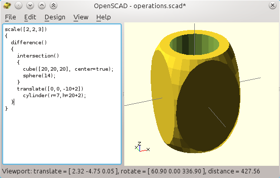
A larger mug by using the scale operator.

We could tweak further the numbers like this, but it is better we now speak about variables instead. This is the object of the next post. Bravo by the way if you made it to here!

Bugging behaviors of Openscad...


Be patient! Sometimes it gets really slow crunching all the numbers. It will most probably not happen with the primitives and operators that were given in this post. But next two posts really can stress your CPU. Some particular construction may also crash the programs, so make sure you save regularly (a good practice whatever the software anyway).

Openscad upgrades are quite rare, but this is not a real issue as it already has most of the necessary tools even for complex designs (you know KISS ?). And even if it has a few "oddities", it really is an extraordinary and productive tool to create parametric engineering designs, for 3D printing or other uses.

Always use comments, so that you can read yourself again next time! And try to keep parts of the design together, that match functions in the final designs (e.g. clearly separated door, hinge, and body).

I wish the CSG manifold constraints are enforced automatically in some cases. It should be possible to know automatically when the the negative shape shall extend slightly beyond the boundary. But for now it is up to you to take care of this. It is extremely important otherwise you may run in trouble with complex shapes when its nasty effects suddenly appears so bad that Openscad refuses to generate the STL with F6!

No ruler, no scale is available on the display and there is no "professional" layout. Quite annoying for any professional usage. Obviously people designed rulers shapes with Openscad itself, but they are slowing things and they are not as convenient as if it was in the software (with automatic numbering according to the scale, etc).
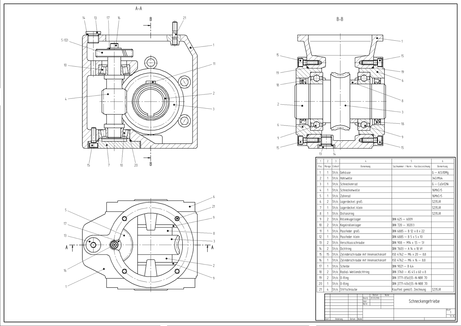
If you need such a professional document, then Openscad is no good.
Local coordinate systems are tricky, especially after rotations. But life is made much simple with the use of the exclamation mark (aka "show only this part of the design"). And... there are better practice with so-called modules, which is part of the next article in this tutorial.

Indeed, if or when you are fine with the concepts shown in this post, you may switch to the next level. It will be all about variables, modules and parametric designs. Just where Openscad starts to get most of its value in my opinion.


How to use Openscad: variables and modules for parametric designs

$
0
0

Part 2/3: Variable and parametric design

So far we used only "hard coded" numbers (see the previous part regarding the basics of Openscad).
Hard coded numbers are mostly always bad. Seriously: when you use Openscad you probably want NOT to use hard coded numbers, but variables instead, as you get lots of advantages in doing so.

A larger mug by using the scale operator (from the "basic" tutorial).
This is still not parametric, as numbers are hard-coded (a bad practice).
For example, the mug above has lots of annoying dependencies: whenever the cube is made taller, the sphere and cylinder parameters must also be updated accordingly.


Better set these number in variables and do some basic math.

A variable is just an alphanumeric tag, usually composed of a set of letters that mean something, and optional underscores (no space is allowed in the name, and numbers may be used but not at the first place).

A variable can be assigned a value, and that can be then used also as if it was a number. There are two advantages to use variables: readability and convenience: set the real number in one place only and never forget to fix other places where the physical value should be used:

  wall_thickness=2;

It is much easier to read a source code that uses variables as you can give meaningful names to them: this "wall_thickness" makes more sense than a number buried in a mathematical expression!

Rewrite the source to be parametric (dependent on variables)

So we are back to our mug, to make it parametric. We also want to drop the global "scale( )" operator because it is quite annoying: since it changes all subsequent axis geometry,  nothing will be "square" anymore so nasty reverse projections would become needed each time we want to use primitives. Better try to use "scale( )" it sparingly and only when required! From now on, we apply it only on a primitive, the sphere, to elongate it vertically so it matches the cuboid (not really a square cube!).

  width=40;
  height=60;
  bottom_thickness=2;
  wall_thickness=5;

  difference()
  {
    intersection()
    {
      cube([width,width,height], center=true);
      scale([1,1,height/width]) // so that Z=1 is now...
        sphere(width/2 * sqrt(2)); // close to the cuboid edges
    }
    translate([0,0,-height/2+bottom_thickness])
      cylinder(r=width/2-wall_thickness,h=height+0.1);
  }


A "good" Openscad source code should almost have no numerical values. Most of the internal stuff is computed out of a minimum set of variables that make sense in the design.

Note: so far, better consider Openscad variables as constants. They can be defined only once at the top of the file or at the top of a module, and not re-defined afterwards.

As shown below, we now generate a new mug or an ashtray just by changing the width and height variables to 40 and 60 mm respectively, or 80 and 20 mm (well, a plastic ashtray is not a good idea).


Two "mugs" made from the same source code: only two numbers need to be changed (height and width)
Parametric designs are probably one of the most important characteristics of Openscad.


Now it still can be made better. Imagine we would like to create a mug with an attached cup below to collect the coffee that overflows. Both the mug and the cup are made out of the above shape.

Export/import STL files

Sure, we could generate the mug, export it to an STL file, and then re-import the STL in our modified source code. Indeed, Openscad knows how to import raw STL files, which is convenient to tweak an existing design for which no source is given (or not compatible with Openscad).

Here is how it would look like here:

A nasty way to import a parametric copy of ourselves, with the "import" function of Openscad and after
the first design was exported as STL. But this is not really the right way to do as we do know the source code!

In fact this was not a proper way to deal with the thing, even if we omit the fact we have a rogue "60" in the source code (the translation of the "import( )" statement, which itself depends on the original size of the mug).

So shall we copy/paste the mug code to get two versions-in-one? Obviously not.

For once, copying/pasting source code is wrong because any bug left in the copied source will be duplicated, and also any subsequent improvement need to be re-inserted in the many copies, that each tend to diverge with time from each other.

Writing a module: recyclable and parametric shapes

Instead of copy/pasting source code, Openscad offers modules that are the right choice here.

The idea of a module is a "functional" shape that accepts a certain number of parameters, just like the primitive shapes do. In fact we are going to create another shape that can be used just like any of these primitive shapes.

Here is how we have to modify our source code:

  module mug(width, height, bottom_thickness=2, wall_thickness=5)
  {
    difference()
    {
      intersection()
      {
        cube([width,width,height], center=true);
        scale([1,1,height/width])
          sphere(width/2 * sqrt(2));
      }
      translate([0,0,-height/2+bottom_thickness])
        cylinder(r=width/2-wall_thickness,h=height+0.1);
    }
  }

This module is there to generate new mug shape (just like cube or cylinder create their respective shapes, but our mug is certainly no more a primitive one). This "mug" shape is created with up to four parameters, that we had previously introduced with the notion of variables.

You may have noticed that two of these parameters have default values, which means they are not compulsory when we create a new mug. This is quite convenient because we probably do not care much about the thickness as long as they are OK. Still, if you give them a value it will be used instead of the default.

Now if you try to run the above, you get nothing new nor updated. In fact the Openscad console tells this:
   ERROR: CSG generation failed! (no top level object found)
This is one more reminder that you should better always leave the console open, or you will not always understand why nothing appears or where something is broken.

The error means "nothing is left to be drawn at the end of the code". And this is true since we just have defined the mug shape, but we created none so far.

So to create our original mug, we would now add the following line, which must be placed outside of the module, for example at the end of the file:

  mug(width=40, height=60);

For the cup/ashtray, it would just be another set of values:

  mug(width=80, height=20);

See how powerful Openscad is becoming? And there are more to come...

Hence, our combined/dual shape can be made by creating two shapes thanks to our module.

By the way, you will see that I also corrected the vertical offset of the mug shape, so that Z=0 corresponds to the bottom of the shape. Nobody wants that the mug is positioned at its middle, as it makes life harder for callers of the mug shape.

You may also notice that no curly braces were used for the added "translate" at the top of the mug module. This is fully OK as there is only one shape that needs to be translated after, namely, the (result of the) "difference" that follows.
Our coupled mug and teacup thanks to a module that builds generic (aka parametric) mug shapes.


  module mug(width, height, bottom_thickness=2, wall_thickness=5)
  {
    translate([0,0,height/2])
      difference()
      {
        intersection()
        {
          cube([width,width,height], center=true);
          scale([1,1,height/width])
            sphere(width/2 * sqrt(2));
        }
        translate([0,0,-height/2+bottom_thickness])
          cylinder(r=width/2-wall_thickness,h=height+0.1);
      }
  }

  // here is the real objects that are made
  union()
  {
    mug(width=40, height=60); // one mug shape1
    mug(width=80, height=20); // another one, different
  }

We can also create and use convenient "local" variables in the module. See below? We added the explicit "r_of_inside". This variable will not be seen at all from the outside of the module, and even though it is used only once at the end of the module, it helps improve readability. Note also that I moved the translation by height/2 closer to the "positive" shape. Carving the cylinder is more easily read without a centering.

  module mug(width, height, bottom_thickness=2, wall_thickness=5)
  {
    r_of_inside=width/2-wall_thickness;
    difference()
    {
      translate([0,0,height/2])
        intersection()
        {
          cube([width,width,height], center=true);
          scale([1,1,height/width])
            sphere(width/2 * sqrt(2));
        }
      translate([0,0,bottom_thickness])
        cylinder(r=r_of_inside,h=height+0.1);
    }
  }

Important note: there are weird restrictions related to variables in Openscad. They recently leveraged a few of them (most notably to allow recursion, i.e. a module calling itself will no fail having separate values). And even though it seems to lack some of these late improvements, I suggest reading this more advanced presentation of variables when you need it, written by +Stephanie Shaltes who regularly post about advanced subjects in Openscad.

Recycling the modules from other Openscad source files

What is nice now, is that you can save the mug module to a scad file and import it and use it as if it was a primitive shape.

To do so you can create a new scad file and tell it to import your former mug scad file. I have to admit that the syntax is stupid given that "include" works as a regular function, why does it need to be otherwise for this one?


  include

Now there is a special comment to do. The above really behaves as if you had copy/pasted the scad source from "mug.scad" in place of the "include" statement. So you will see the mug-with-a-cup that was defined above.

There is another, probably more useful may to recycle your old file, by using another function like this:

  use 
  mug(width=40, height=60);

This time, the "use" statement only imports the definition, including the modules, that were defined in "mug.scad". It will just not execute anything else. So the "use" statement generates no shapes on its own, even though there may be some in "mug.scad" (as we have). This is quite convenient because it leaves the possibility to have "mug.scad" do something on its own (e.g. just to show working examples as we did), without polluting the new code here.

Note: there are a lot of almost-official modules, in a library named MCAD. It brings many shapes and standard nuts, bolts and other industrial equipment. It is free just as much as Openscad, and the source code is here.

Convex hull: creating complex shapes with basic ones.

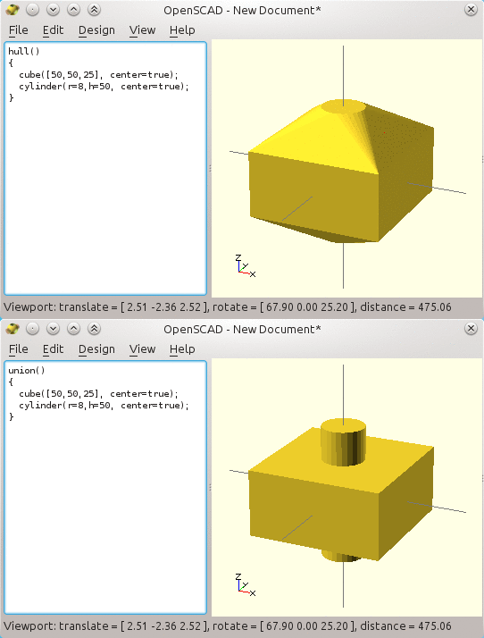
Now, life with Openscad would not be possible with one more operator (at least): the convex hull.
Think of it as the shape that you get when you wrap a plastic around a bunch of shapes with no resulting concave parts.

A sample will make this clear:
  hull()
  {
    cube([10,10,10], center=true);
    translate([20,0,0]) sphere(r=3);
  }

Below you get an animation that changes from a regular "union( )" to a "hull( )".
Animation showing the effect of "hull( )", aka "convex hull".

Usually no "complex" shape is used within a hull. But there are often more than two primitives. here is one case: to build a cube with round corners for example.
Note: there are many way to build such a shape, and using a hull is somehow overkill: a union is enough, as we will see after. Anyhow, this is just an illustration of the use of hulls.

  hull()
  {
    translate([-10,-10,0])
      cylinder(r=8,h=50, center=true);
    translate([10,-10,0])
      cylinder(r=8,h=50, center=true);
    translate([-10,10,0])
      cylinder(r=8,h=50, center=true);
    translate([10,10,0])
      cylinder(r=8,h=50, center=true);
  }

Do not forget that you can prefix a shape with % or # when you want to check its individual contribution to the union!

One way to build a (partially) rounded cube.
We will do this better as we will see!

There are two improvements to do here. First, a hull is a lengthy operation, where Openscad need to compute a lots of stuff. It is usually kept for shapes that cannot be achieved otherwise.

Here, the above is much faster with a simple union of 4 cylinders and 2 cuboids, this way:

  union()
  {
    translate([-10,-10,0]) cylinder(r=8,h=50, center=true);
    translate([10,-10,0])  cylinder(r=8,h=50, center=true);
    translate([-10,10,0])  cylinder(r=8,h=50, center=true);
    translate([10,10,0])   cylinder(r=8,h=50, center=true);
    cube([20,20+2*8,50], center=true); // space left inside
    cube([20+2*8,20,50], center=true); // and in the other way
  }

Then, a second improvement can be made because this is not a proper way to code anyway. There are lots of copy/pasted code as you can see, that ought to be better made with loops.

This is the subject of the third article, about advanced CSG techniques in Openscad (in progress).

Fortune 500 teller? 3D printing trends, reports, analyses and business intelligence...

$
0
0

Are the "high-level strategically analyzed reports" worth something?

Hey, could my blog be so informative? :)

I am regularly contacted, mostly on linkedIn, by experts that seek data. The last time it was for a company that compiles data and trends "for the Fortune 500 companies". Which does not excite me more than that, and here is why.

Such data are usually sold at an incredible price to managers that think they would get a better clue at the market, with the idea that they would be more profitable. But there are two traps here.

The first one is: am I really enough of an expert to give clues to Fortune 500 companies? I am mostly an iconoclast, e.g. when I say not to invest in Makerbot at all (neither as a customer nor as an investor, but I have a full-length analysis why I say so), or when I explain why, imho, "pro/expensive" FDM printers are almost a scam nowadays. OK, I may be better than a monkey and provide a few useful reviews (e.g. materials for artists, or what cannot be 3D printed...). But still, asking my opinion on the market trends could cast a doubt on the forthcoming corresponding report. Oh, well, may be they also want data from makers -- why not after all.

As a manager, do you really need accurate trends and data?
Or do you need only the feeling that you have some?
Secondly and as importantly, the reviews are most often never used in reality. Once bought, they are dropped on the desk of a subordinate in the company, with the advice to get some insight from the document. The underlying idea is: since it is expensive it must be valuable...


Eventually, the report ends its life miserably in the darkness of the drawer together with a set of abandoned goodies, at the desk of someone further down in the hierarchy... precisely at the level where no more cares about its content.

For sure, most of the engineers have no big consideration for business compilations, precisely because they know how often and how badly experts fail to predict any trend.  But it would also be against the company policies to tell upwards though, so things stay unchanged and lots of money is wasted in the process.

And yes, I do know a few companies that do have lots of dusty compilations like these. By the way, these are soon obsolete (of course you get a discount if you subscribe to the thing...). 

Hey, where is my money?

Back to the guy who contacted me and another reason I did not answer. He basically tells me they would make a pile of money out of the opinions of other people like me. And meanwhile, he tells me they would not pay for the collected data. Oh, sure, I would have a "special offer" on the resulting document. This may be the usual practice, but I disagree nonetheless and it casts another shadow on the seriousness of the document.

By the way my name most probably would be stripped off the document in the end, so my ego would not get paid either. I just cannot imagine the guy telling at the end he got some of his insights from a blogger at www.tridimake.com ;)

And finally, it was easier for me to decide that I would keep on making my opinions public and free, instead of feeding a closed and dubious system. Do not believe too much in the fortune 500 tellers ;)

Conclusion: what I think about consulting firms, trends and reports

I bet no analyst ever predicted this!
From Geek&Poke by Oliver Widder
As a manager I was always highly suspicious of costly external data trend and analyses. I would often better trust both my nose and my employees (that's how business is started anyway). Relying on external views that you cannot assess is uselessly risky in my opinion, and there are tons of heavy historical mistakes made by analysts that highlights it. Also relying on others for one's own strategy and evaluation skews the whole business, it puts everyone in the same bag, and eventually it can fail so hard as to provoke a huge crash of the economy (see, e.g. the paragraph on AAA backfire from this nobel laureate).


Now, as an individual, it boils down to whether I consider myself such an expert on the market of 3D printing, and whether I should help building such reports for free... I certainly can tell for the last one: no, I will not feed the trolls. And actually I do not care if I am a "valuable" expert for Fortune 500 companies. I would better help smaller companies.


So if my answer below brings one smile on your face, then you will not make me richer but you will still make my day:

Hello,
Thanks a lot for your attention. I am however really too busy for an exclusive interview in the next weeks.
I would gladly help, but I would better share my opinion on my popular blog.
Still, please feel free to provide me with some specific questions that you would like me to address. I would reply to you specifically for what I think would not fit on my blog.
best regards, 
Jérémie

And unsurprisingly, I got no subsequent email after my answer. Time is money, isn't it ?


For reference, here is the email I first got from linkedIn:


On 09/24/13 12:51 AM, xxxxx wrote:--------------------
Dear Jeremie F, 
Greetings for the day! 
Allow me to introduce myself as a Research Analyst at MarketsandMarkets, a global market research and consulting firm based in the U.S. We, at MarketsandMarkets, publish high-level strategically analyzed reports for over thirteen industry verticals and serve as a business intelligence partner to Fortune 500 companies across the world. We are studying the ”Global 3D printing materials by Types, Applications and Geography, 2011 - 2020” Market and would be publishing a syndicate market research report on it in November 2013. 
Currently, we are in the phase of conducting interviews with some of the industry experts in this market to understand the latest market trends. We understand that you are an expert in this market and hence your views and suggestions will be really insightful and valuable for us. 
Following are the major points on which I would like to understand your perspective on the 3D printing materials market: 
1. Current and future market trends of the market 
2. Growth rate and market size of the market 
3. Applications of 3D printing materials, Drivers & restraints of the market. 
During this process, we would share our findings and invite your valuable opinion for the same. Once the report is published, we will also share the executive summary and key findings as a token of appreciation. Also, if interested in purchasing the report a special discount will be offered to you. 
Kindly suggest a convenient date, time and contact number to reach you. Feel free to forward this mail to your colleagues who would be interested in joining the discussion. 
I look forward to hearing from you. Thank You. 
Best Regards, [xxx][yyy]

How to use Openscad (3): iterations, extrusions and more modularity!

$
0
0

Part 3/5: iteration, extrusion and useful parametrized CSG techniques

Repeating shapes

As we saw in the previous article, repeating a shape by copy/pasting its Openscad definition is a bad practice. It increases the risk of mistakes just because of the slight changes that have to be made on each of the copies. Any "regularity" should be factorized, and let the computer do our work!


The former way we built a (partially) rounded cube. Four copy/pastes? Boo!

See how the four columns really are all the same cylinder, where only the position changes? This is where we can and we should use loops instead. And once again there are different ways to do so.
The "for( x = range ) block;" repeats the block once with x set to each of the given values in the range, just like if Openscad was automatically copy/pasting the command block.

Ranges may be a list of values, separated by a comma, like this (one loop within another loop):

  union()
  {
    for(x=[-10,+10]) // repeat the following with two variants for x
    {
      for(y=[-10,+10]) // repeat again but this time for y
      {
        translate([x,y,0])
          cylinder(r=8,h=50, center=true);
      }
    }
    // two more shapes
    cube([20,20+2*8,50], center=true);
    cube([20+2*8,20,50], center=true);
  }

What goes on here?

Openscad sets x to the first value of its range -10, then does the same with y (to its first value, -10 also).
Then, within the inside loop, it does a translation to (x,y) and adds a cylinder there.
Once done, it loops with the second value of y (it sets y to +10), and adds another cylinder at (-10,10).
When it reaches the end of the y range, it loops on x next time, with x=+10 and so it does again a loop on y=-10 and y=+10.

Overall, the inner cylinder will be created four times at the four places! Hence the result that looks like exactly as we did previously, but without the repeated code.

This writing is more compact, and it helps to convert the source code to a more compact and parametric version: the size and roundness are now variables, that are set once at the beginning.

I would write it this way, to minimize the presence of the value 10. The idea really is to put 4 cylinders around the vertical axis at the same distance. This distance should be seen only once for more readability and easier parametrization.

 See how the remaining of the code becomes both generic and more readable?

  size=20;
  roundness=8;
  height=50;
  union()
  {
    for(x=[-1,+1])
      for(y=[-1,+1])
        translate([x*size/2,y*size/2,0])
          cylinder(r=roundness,h=height, center=true);
    cube([sizesize+2*roundnessheight], center=true);
    cube([size + 2*roundness, size, height], center=true);
  }


We already used vectors when specifying the three X,Y,Z arguments used to define cubes or translations for example. These are just vectors of 3 values. Note how they can be stored themselves in variables:

  cube_size=[20,10,5]; // a triplet, aka 3-item vector stored
  cube(cube_size); // ...in a variable, used to create a cube!

The "for" loops also deals with vectors like [v1,v2,v3,v4], but we can benefit from a few additional variations, in order to improve the 4-cylinder example further.

Less code almost always means less bugs: a range can be specified as a list of values as above, but it can also be defined by a [start:step:stop] triplet. This is done below, where r is set in turn to 0, then 90, and finally 180. We stop "at" 359°, i.e. before reaching 360° that be at the exact same place as 0°.

We then use "r" variable to rotate around the Z axis, and behave as if we were adding a column at (10,10). This absolute coordinate is in fact "rotated" on each of the symmetrical points.

  size=20;
  roundness=8;
  height=50;
  union()
  {
    for(r=[0:90:359]) // stop *before* 360° (as 360°=0°)
      rotate([0,0,r])
        translate([size/2,size/2,0])
          cylinder(r=8,h=height, center=true);
    // same technique for the "inside" cuboids:
    for(r=[0,90])
      rotate([0,0,r])
        cube([sizesize+2*roundnessheight], center=true);

  }

There are still other ways to create the same design (eg. by intersections, and so).

I tend to prefer either rotation, or inverted axes (with the scale operator and -1 on some axes). A translation like we did previously is probably not the wisest choice because it does not change the "orientation" of the duplicated object itself, as you can see below with a shape that is no more a cylinder.

Translations will keep the same positive orientation for the four parts!

Rotation is often preferred as it also "fixes" the orientation of the duplicated part.

Scaling operators are also useful to invert axes (click to see the code).

Recursive designs, and conditionals

Only the latest version of Openscad made recursion possible. Previously, variables had the amazing property that they were ... constant! Advanced operators like "assign( )" helped circumvent some of the issues, but they made the source code even worse in my opinion.

What is recursion? Well, it happens when a module calls itself in order to build more versions of its own shape, smaller or in another place. To avoid looping indefinitely (and killing the computer memory and CPU), we must also introduce conditionals. A test will be made to stop calling ourselves after some condition is met, e.g. like when the part becomes too small.

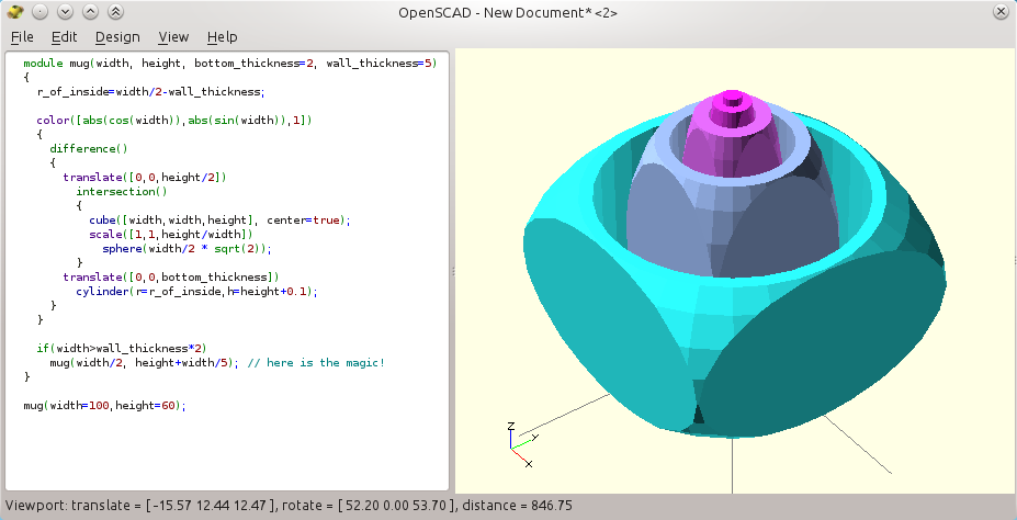
Remember the mug-with-a-cup that we made in part two? Here is how we can write a recursive mug, that will add smaller-mugs-in-mugs till it get smaller than the constant wall width. It would not make any sense to go "deeper" in the recursion anyhow.

A recursive mug. Make sure you have a version of Openscad that allows this
(an indicator is that the syntax is now colored: another long-waited feature!)
By the way, you see also the use of the "color" operator, that highlights each of the sub-mugs. The color components were chosen according to the size of the mug, so we get an automatic color gradient whatever the depth of the recursion.

  module mug(width, height, bottom_thickness=2, wall_thickness=5)
  {
    r_of_inside=width/2-wall_thickness;
    echo(width); // print the value in the console
  
    color([abs(cos(width)),abs(sin(width)),1]) // color with size
    {
      difference()
      {
        translate([0,0,height/2])
          intersection()
          {
            cube([width,width,height], center=true);
            scale([1,1,height/width])
              sphere(width/2 * sqrt(2));
          }
        translate([0,0,bottom_thickness])
          cylinder(r=r_of_inside,h=height+0.1);
      }
    }
    // At this stage we are back to the default union() behavior
    if(width > wall_thickness*2) // only is there is room
      mug(width/2, height+width/5); // add a smaller mug here
  }

  mug(width=100,height=60); // calling the top object

If you still get only one mug, check the console for an error like "WARNING: Ignoring recursive module instanciation of 'difference'.". This would tell that your version of Openscad does not support recursion and that you should probably upgrade. In the "Help / About" menu, check that the version is more recent than the 2014.01.29 (e.g. the 2014.04.02 as above).


Also the generated sizes are now harder to track, so we used the echo command to show how to get the value of width each time the module is called:

  echo(width);

After you refresh the design, the console dumps the following:
  ECHO: 100
  ECHO: 50
  ECHO: 25
  ECHO: 12.5

  ECHO: 6.25


Important note: the very weird properties of variables in Openscad will not be discussed here. Even though recursion was recently allowed and not discussed in the following document, I highly suggest reading this detailed presentation of variables when you need it, written by +Stephanie Shaltes. By the way, she regularly posts about advanced subjects in Openscad so she may be interesting to follow on G+.

Advanced concepts

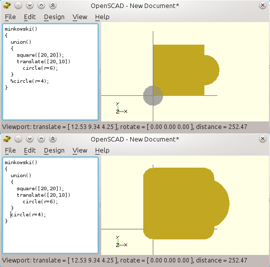
The minkowski operator is quite cool. But it is so slow that we almost never use it. The effect is like when a shape is used to paint or "brush" a parent shape: e.g. a small sphere will "round" all the edges and surfaces of a given reference object.

Shown below is an example where we use only 2D shapes, that Openscad also supports (we then use square in place of cube, circle for spheres and so).

The minkowski operator, illustrated here on 2D Openscad shapes.
It does works in 3D also but is so slow that the shape is usually better designed otherwise.

More importantly, there are also two kinds of extrusions, linear and circular, that makes 3D shapes out of 2D shapes.

They are very useful to create 3D shapes out of "industrial" 2D designs (often based on the Autocad DXF file format that Openscad knows how to import).

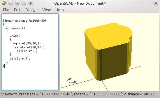
Here we will "raise" our former 2D shape vertically and make it a 3D shape, here is what we write:

  linear_extrude(height=30)
  {
    minkowski()
    {
      union()
      {
        square([20,20]);
        translate([20,10]) circle(r=6);
      }
      circle(r=4);
    }
  }


3D linear extrusion of the former 2D shape


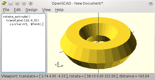
Contrary to the linear extrusion, the rotate_extrude( ) operator can be used to create a "ring" out of a 2D profile. This is how we extrude a rough circle into a torus (note how the circle must be translated out of the origin to do so!).

Rotational extrusion of a basic 2D hexagon (a 6-segment circle)
 For the most curious readers, these extrusion operators have trickier optional properties (see the official documentation for more on this). If you cut the toroid by an orthogonal plane you will find the 6-segment primitive circle (hence the rough look).


One annoying thing with the "rotate_extrude( )" is that it does make partial rotation. It will always "close the loop".

So when you need only 1/4th of a turn (i.e. a partial 90° rotation), say, then the best way is to intersect the shape with a cube, like this:
Easy 90° slice of the torus, with an intersection of the former torus
and a big cube that stands in the positive (X,Y,Z) spatial quadrant.

Now, for any angles smaller than 90°, we can create a "wedge" shape by means of a convex hull around two very thin slices (almost flat cuboids), where one of them is rotated by the expected angle (see, by the way how modules can be defined within modules).
A 45° "slice" of the initial torus, but it works only with for small wedges.
The "wedge_wall" thickness should be chosen below the 3D printer resolution, e.g. as low as 0.02 mm. But take care as too small a value and Openscad may just "skip" the shape!).

You may have seen the use of the weird expression (center==true ? -height/2 : 0). This is a compact form of a conditional, usually barely readable: "if center is true, then replace the expression by the value -height/2 else use the value 0". This is a short way to code a condition, which is used here to shift the part downwards by half the height in order to center it, like it is done with cylinders.

We did not use a more usual "if" test, as in the recursive mug. It would make life harder as "if" works with shapes, and not operators: the "if" condition cannot apply on the presence of the "translate" operation itself, but only on whole shapes. The "?" shorter version applies only on mathematical expressions, suitable here. All in all, in some case we will ask for a translation of (0,0,0), which works!


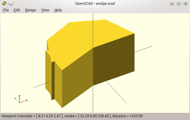
Anyhow. The above wedge design fails when the angle is larger than 90°, as the hull will flatten the two-wall wedge (see the animation below).
A convex hull between the first and
last "wall" fails with any large angles!
We will see Openscad animation later.

To create a pseudo-wedge that really can span 360°, we can use a succession of hulls no bigger than 45°, and that are progressively rotated around the Z axis.

So using a loop is very natural to generate the intermediate walls, spaced here at 45° of each other.
Still, we need to add the last wall "manually" as it may not fall on a multiple of 45° as below.
Angularly-spaced thin wall to help building the required concave wedge.

  module wedge(angle, extent=100, height=100, center=true)
  {
    module wedge_wall()
    {
      translate([0,0,(center==true ? -height/2 : 0)])
        cube([extent,0.1,height]);
    }
    
    for(r=[0:45:angle-1])
      rotate([0,0,r])
        wedge_wall();
    rotate([0,0,angle])
      wedge_wall();
  }

  wedge(angle=200);


Now, we want a shell somehow like a hull around this skeleton...

But a regular hull( ) around the thin walls would fail badly, as it would "fill" also straight from the first wall to the last wall. The required concavity made by the first and last walls would not be respected. Sure, as the operator builds a convex hull. A concave hull probably has no meaning anyway, we must build it by hand.

So what's the trick? The expected concave wedge shape can be made by unions of successive hulls!

Here is our first attempt at a potential "concave" wedge.
It works but it makes a dirty source code (so far).
This is how we did it. We also introduces the min(v1,v2,v3..) and max() mathematical operators (weirdly, they do not take a vector as argument but a list of variables).

  module wedge(angle, extent=100, height=100, center=true)
  {
    module wedge_wall()
    {
      translate([0,0,(center==true ? -height/2 : 0)])
        cube([extent,0.1,height]);
    }
    
    for(r=[0:45:angle-45-1])
    {
        hull()
        {
          rotate([0,0,r]) wedge_wall();
          rotate([0,0,min(angle,r+45)]) wedge_wall();
        }
    }
    hull()
    {
      rotate([0,0,max(0,angle-45)]) wedge_wall();
      rotate([0,0,angle]) wedge_wall();
    }
  }

  wedge(angle=200);

The min and max are required to avoid overshooting the expected wedge angle.

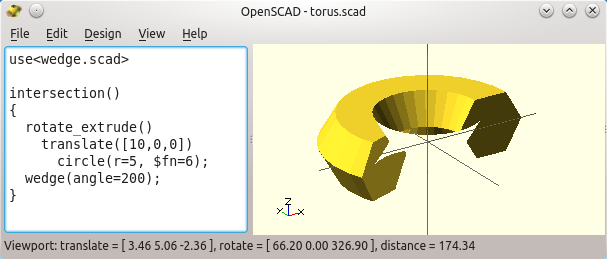
Here are the result of the intersection of our wedge and the initial torus, that finally does it.

It works! The parametric wedge "sliced" the torus the way we wanted.
Note the "missing" part? It is only a rendering issue, see below!

Here is why there is a "convexity" parameter in the rotate_extrude(), and a few other
Openscad functions. It helps the renderer by telling to look deeper in the intersection of objects.


Well... OK, it works... but the source code got much polluted...

It can get cleaner with the beautiful and somehow forgotten / unusual concept of children in Openscad. And that will make yet another part in this introduction to Openscad (to come!)


How to use Openscad (4): children and advanced topics

$
0
0

Part 4/5: children, factorized placement and chained hulls

Yes, it was made with Openscad and it is parametric!
(extreme collaborative work, picture by N.Goodger)
Previously in this tutorial for the Openscad CAD software, we talked only about modules that behaved as shapes.


A powerful and often ignored feature of Openscad is that modules can also behave as if they were operators, exactly like the translate()or color() operators. They do not create shapes on their own, but they modify the subsequent commands.

In Openscad, it is possible through the use of children. But first, let us create and discuss a bit about a common-case example.


This article is part of a longer serie:
  1. Introduction to constructive solid geometry with OpenSCAD
  2. Variables and modules for parametric designs
  3. Iteration, extrusion and useful parametrized CSG techniques
  4. Children, factorized placement and chained hulls

How can "negative" shapes extend outside of their module?

This is a common design problem with the constructive solid geometry paradigm.

Let us consider a support for an electronic board. Each of the "pegs" is made of a cylinder, a bevel at the base, and a hollow cylinder for the screw. We conveniently put all these in a "peg" module.

But we want the screws to go all through the support, which itself it added outside of the module...

Failed! The peg holes do not go through the blue plate...
Forget about the dimensions, we do not care here.

As we have seen, it is a good practice to factorize the peg shapes into a module, and then to iterate four times on it, like this:

screw_dist=40; // PCB hole spacing (square)
height=10; // peg height
peg_d=20; // peg diameter
screw_d=10; // hole diameter
plate_th=1; // plate thickness
tol=0.05; // used for CSG subtraction/addition

module one_peg()
{
  difference()
  {
    union()
    {
      // main cylindrical body
      cylinder(r=peg_d/2,h=height);
      // with a tronconic base (bevel)
      cylinder(r1=peg_d/2+2,r2=peg_d/2,h=5);
    }
    translate([0,0,-tol]) // screw hole
      cylinder(r=screw_d/2,h=height+2*tol); // through hole
  }
}

// Helper module: centered cube on (X,Y) but not on Z, like cylinder
module centered_cube(size)
{
  translate([-size[0]/2, -size[1]/2, 0])
    cube(size);
}

// Now call and build the four pegs
for(r=[0:90:359])
  rotate([0,0,r])
    translate([screw_dist/2,screw_dist/2,0])
      one_peg();

color([0,0,1])
  translate([0,0,-plate_th])
    centered_cube([
      screw_dist+peg_d*2,
      screw_dist+peg_d*2,
      plate_th+tol]); // slightly higher to avoid gaps


But when we add the blue bottom plate, flush with the pegs, the holes are no more open!

So how do we fix this?


Making holes longer will not help, because they apply only to the shapes defined in the one_peg module (i.e. only the cylinders and before the plate is added).

A way out could be to take the negative (hollow) cylinder out of the module, and remove them to the union of the pegs and the plate. But it breaks the very idea of a module by sharing "internal" information with the outside (it crosses the module encapsulation). It also makes the source code not very readable and less parametric.

Or the module itself could be written with a "positive" and "negative" version like this. The changes are highlighted.

screw_dist=40; // PCB hole spacing (square)
height=10; // peg height
peg_d=20; // peg diameter
screw_d=10; // hole diameter
plate_th=1; // plate thickness
tol=0.05; // used for CSG subtraction/addition

module one_peg(positive_shape=true)
{
  if(positive_shape)
  {
    // main cylindrical body
    cylinder(r=peg_d/2,h=height);
    // with a tronconic base (bevel)
    cylinder(r1=peg_d/2+2,r2=peg_d/2,h=5);
  }
  else // "negative" shape (carve the inner peg cylinder)
  {
    translate([0,0,-tol -plate_th]) // screw hole
      cylinder(r=screw_d/2,h=height+2*tol + plate_th); // hole
  }
}

// Helper module: centered cube on (X,Y) but not on Z, like cylinder
module centered_cube(size)
{
  translate([-size[0]/2, -size[1]/2, 0])
    cube(size);
}

difference()
{
  union()
  {
    // Now call and build the four pegs positive shapes (not carved)
    for(r=[0:90:359])
      rotate([0,0,r])
translate([screw_dist/2,screw_dist/2,0])
 one_peg(positive_shape=true);

    color([0,0,1])
      translate([0,0,-plate_th])
centered_cube([
 screw_dist+peg_d*2,
 screw_dist+peg_d*2,
 plate_th+tol]); // higher to avoid gaps with the pegs!
  }

  // And finally carve the pegs (all through the plate itself)
  for(r=[0:90:359]) // repeat the positioning
    rotate([0,0,r])
      translate([screw_dist/2,screw_dist/2,0])
one_peg(positive_shape=false);
}

Now there is something annoying: positioning the "positive" peg shapes and the "negative" peg shapes rely on fully duplicated code. This is bad.

Indeed, any change in the positioning would need to be duplicated. Bug fixes also! Duplicating code adds uninteresting codelines and it is prone to bugs, because a bug fix may be forgotten as the programmer does not know where and how many times the code was duplicated. It soon becomes very hard to maintain and upgrade such a design!

This is why I often use a "placement" module for the location of the pegs.


Referring to the children of a module: how it works

This is a somehow tricky but very powerful Openscad feature.
It is not usually found in other languages, which may be the reason why it is too often overlooked by programmers who use openscad.

Now, it is extremely powerful as it makes the source code much cleaner, and it allows many optimizations.

In practice, when you are in a module, Openscad creates two special variables for you, that refer to the shapes that are in the scope of the module when it gets used.
   children - an vector that holds reference to each of shapes that are impacted by the module
   $children holds the number of shapes that follows the module use

To get an indivudual value of a vector in Openscad, you can use this syntax:
  children(i)

Now, the first children of the module will start at index zero (not one!). So the last children really is children($children-1). Accessing the vector at index $children is an error, just like trying to use a negative number. This is the norm in most of the programming languages when dealing with arrays: the first item is at index zero.

So what is a child now? It is any primitive or composed shape that appear right "under" the module call itself.

Check the example below, where translate_children() iterates on its children, so as to translate each of them on the X axis by a value which is proportional to their order of appearance, before "calling them":

Efficiently translating the "children" of a module proportionally to their order of appearance!

Now, a children really is a shape that is "just below" the module. In the following, the cube and the cylinder are seen from within the module as a single child object (which they really are!)

Children are really only at the top level withing a module!
For the same reason, the iteration below is also one single "unioned" object for the module. It does not see the individual sub-shapes!
Hence, the $children feature does not "see" the individual cubes either (they were merged beforehand)!
The last case occurs because for does an implicit union on the items. This problem is highlighted by the weird but required intersection_for() in the official documentation, that will be of no help here though...

A module as a positioning tool: using the children array


Back to our PCB holder... Thanks to Openscad's $children feature, we now can factorize both the duplication and the placement of each of the four individual pegs. Here again the changes are highlighted when compared to the previous source code.

We do it this way:

screw_dist=40; // PCB hole spacing (square)
height=10; // peg height
peg_d=20; // peg diameter
screw_d=10; // hole diameter
tol=0.05; // used for CSG subtraction/addition
plate_th= 1;

module peg_positions()
{
  for(r=[0:90:359]) // it will make 4 versions of the sub-shapes
    rotate([0,0,r])
      translate([screw_dist/2,screw_dist/2,0])
      {
for(i=[0:$children-1])
          children(i); // do each of the shapes that come after us
      }
}

module one_peg(positive_shape=true)
{
  if(positive_shape)
  {
    // main cylindrical body
    cylinder(r=peg_d/2,h=height);
    // with a tronconic base (bevel)
    cylinder(r1=peg_d/2+2,r2=peg_d/2,h=5);
  }
  else
  {
    translate([0,0,-tol -plate_th]) // screw hole
      cylinder(r=screw_d/2,h=height+2*tol + plate_th); // hole
  }
}

// Helper module: centered cube on (X,Y) but not on Z, like cylinder
module centered_cube(size)
{
  translate([-size[0]/2, -size[1]/2, 0])
    cube(size);
}

difference()
{
  union()
  {
    // Now call and build the four pegs
    peg_positions()
      one_peg(positive_shape=true);

    color([0,0,1])
      translate([0,0,-plate_th])
        centered_cube([
          screw_dist+peg_d*2,
          screw_dist+peg_d*2,
          plate_th+tol]); // higher to avoid gaps with the pegs!
  }

  // And finally carve the pegs (all through the plate itself)
  peg_positions()
    one_peg(positive_shape=false);
}

What happens here? The module peg_position() does not create any shape on its own. Instead it does all the work to duplicate and position each of the pegs, and only then it refers to its own children to do something. We have a unique  children here each time, a call to the one_peg() module.


Here we are. Through-holes for the PCB pegs.

To conclude this part, we can merge everything in a single compact module, with an "action" argument. I generally do it this way:

screw_dist=40; // PCB hole spacing (square)
height=10; // peg height
peg_d=20; // peg diameter
screw_d=10; // hole diameter
tol=0.05; // used for CSG subtraction/addition
plate_th= 1;

module peg(action)
{
  if(action=="position")
  {
    for(r=[0:90:359])
      rotate([0,0,r])
translate([screw_dist/2,screw_dist/2,0])
{
 for(i=[0:$children-1])
   children(i); // do the shapes that come after us!
}
  }
  else if(action=="add")
  {
    // main cylindrical body
    cylinder(r=peg_d/2,h=height);
    // with a tronconic base (bevel)
    cylinder(r1=peg_d/2+2,r2=peg_d/2,h=5);
  }
  else // "remove"
  {
    translate([0,0,-tol -plate_th]) // screw hole
      cylinder(r=screw_d/2,h=height+2*tol+plate_th); // through hole
  }
}

// Helper module: centered cube on (X,Y) but not on Z, like cylinder
module centered_cube(size)
{
  translate([-size[0]/2, -size[1]/2, 0])
    cube(size);
}

difference()
{
  union()
  {
    // Now call and build the four pegs
    peg("position")
      peg("add");

    color([0,0,1])
      translate([0,0,-plate_th])
        centered_cube([
          screw_dist+peg_d*2,
          screw_dist+peg_d*2,
          plate_th+tol]); // higher to avoid gaps with the pegs!
  }

  // And finally carve the pegs (all through the plate itself)
  peg("position")
    peg("remove");
}


The result is a code which is much more readable, and more useful. Still one has to split the added shape and the subtracted shape, and it must be taken into account. The "remove" part must be positioned correctly in the CSG tree, after the plate is merged with the positive peg shapes.

Now, whenever other shapes must be positioned relatively to the pegs, we can use the convenient peg("position") module call, and group the shapes in a union that will be "preprocessed" by the module.


Another very useful use of children : "Serial hull", aka "chained hull"


Remember the wedge in our previous post? It was built out of "support walls" to intersect a torus and leave only a variable sector.  We had to revert to sequence of pairs of convex hulls in order to create the appropriate (concave) final shape.
The support structures we used to build a wedge shape that we used
to intersect a torus made from a fully circular rotate_extrude().

The deal here would be to create a module that does the union of a sequence of hulls in a list of children. Let us call this special module "serial_hull( )".

Calling it this way:

  serial_hull()
  {
    thin_wall1();
    thin_wall2();
    ...
    thin_wall7();
  }

...would create a convex hull of the shapes 1 and 2, then another hull with the shapes 2 and 3, and so. The resulting convex hulls would then be merged (with the default union operation).

See how the union of many hulls is definitely not like the hull of all the shapes at once?

Using loops, it becomes straightforward to implement:

  module serial_hull()
  {
    // let i be the index of each of our children, but the last one
    for(i=[0:$children-2])
      hull() // we then create a hull between child i and i+1
      {
        children(i); // use child() in older versions of Openscad!
        children(i+1); // this shape is i in the next iteration!
      }
  }

Note that we can now join any kind of shapes:
  
  serial_hull()
  {
    cube(10,center=true);
    translate([20,0,0]) sphere(10);
    translate([30,0,0]) sphere(5);
  }

Linking a cube, a large sphere, and a smaller one with a union of consecutive convex hulls, the pretty way!

Note
: if you are using an old version of Openscad you will have to use "child(index)" in place of "children(index)" (they just changed the name of the variable for more consistency).
Reciprocally, you can use "child" is a newer version, but you will get a warning stating "DEPRECATED: child() will be removed in future releases. Use children() instead.".


So will it help our parametric wedge, to build a partial "rotate extrude"?


Now let us try and go back to our partial torus... It will fail if we try naively...

Remember, we have seen the issue in the introduction to $children above: the module sadly considers the for loop on the wedge_wall() as a single child, and not as separate shapes.

module chained_hull()
{
  for(i=[0:$children-2])
   hull()
   {
     children(i);
     children(i+1);
   }
}

module wedge(angle, extent=100, height=100, center=true)
{
  module wedge_wall()
  {
    translate([0,0,(center==true ? -height/2 : 0)])
cube([extent,0.1,height]);
  }

  chained_hull() // will this create consecutive hulls? NO!!
  {
    for(r=[0:45:angle-1]) // implicit union of all the items!!
      rotate([0,0,r])
        wedge_wall();
    rotate([0,0,angle]) // this is only the second child!
      wedge_wall();
  }
}

wedge(angle=270);


In fact, and I would like to be corrected, I do not know how we could use $children and "exploded" for loops at the same time.


So far, the most compact version I could make is to build the angular sector this way, where some thin walls may be stacked on each other at angle "angle" (no harm with respect to CSG manifold policies).

module chained_hull()
{
  for(i=[0:$children-2])
    hull() // here we do it another way (without a secondary loop)
    {
      children(i);
      children(i+1);
    }
}

module wedge(angle, extent=100, height=100, center=true)
{
  module wegde_if(sub)
  {
    // Revert to angle zero in case the provided one "sub"
    // exceeds the wedge maximum angular size "angle":
    rotate([0,0,( angle>sub ? sub : angle)])
      translate([0,0,(center==true ? -height/2 : 0)])
cube([extent,0.1,height]);
  }

  chained_hull() // explicit children makes it work...
  {
    // Create the appropriate thin walls each 45° around Z
    // They cannot be made with a "for" loop b/c of the implicit
    // union it does, which would fail with the chained_hull()
    wegde_if(0);
    wegde_if(45);
    wegde_if(45*1);
    wegde_if(45*2); // wedge_if() "flattens" sections that are
    wegde_if(45*3); // past the user-provided "angle", so only
    wegde_if(45*4); // the right number of sections will be
    wegde_if(45*5); // generated!
    wegde_if(45*6);
    wegde_if(45*7);
    wegde_if(45*8); // this last one is "chopped" to "angle"
  }
}

intersection()
{
  rotate_extrude(convexity=10)
    translate([40,0,0])
      circle(r=30);
#  wedge(angle=240); // "dash" to see it as below!
}


As can be seen, we eventually designed our partial but generic torus!

One last attempt to get rid of the manual repetitions: if/then readability issues


As usual there are numerous ways to achieve the same goal. We can use only convex wedges and decide either to intersect or to subtract it from the torus. This way we also can rely on for-loops to build the wedge and stay compatible with the chained_hull()...

But if/else constructs are usually considered bad practice because they disrupt the CSG tree.
Also, because of restrictions in the CSG algorithms, they cannot apply only to the choice of the operation (intersection versus difference), so as to keep a common "content".

For example, the following is illegal. It will not compile:

if(condition)
  intersection()
else
  difference()
{
  cube([100,100,100],center=true);
  sphere(r=55);
}

This is why using if/then does generally not help to keep the code factorized. It should be written like this, repeating the content twice :(

if(condition)
  intersection()
  {
    cube([100,100,100],center=true);
    sphere(r=55);
  }
else
  difference()
  {
    cube([100,100,100],center=true);
    sphere(r=55);
  }

This is why I tend to favor the former use of valued conditionals like (test ? then_value : else_value) where only values are changed and not the operations. There is a second reason in my opinion: it tends to be faster when rendering the design (probably because cache and optimization are more efficient on a static CSG tree).

Anyhow, here is the variant with only convex wedges, which is nonetheless more parametric (there are no more "hand placed" thin walls at each 45°).
By the way, we made the wedge_this now a modifier on its own:

module chained_hull()
{
  for(i=[0:$children-2])
    hull()
    {
      children(i);
      children(i+1);
    }
}

module wedge_this(angle, extent=100, height=100, center=true)
{
  module convex_wedge(a) // compact but works ONLY for a<=180°
  {
    translate([0,0,(center==true ? -height/2 : 0)])
      chained_hull()
      {
for(r=[0:45:a-1]) rotate([0,0,r]) cube([extent,0.1,height]);
rotate([0,0,a]) cube([extent,0.1,height]);
      }
  }

  if(angle<=180) // then intersect the wedge with the children
  {
    intersection()
    {
      for(i=[0:$children-1]) children(i);
      convex_wedge(angle);
    }
  }
  else // else subtract the reciprocal wedge from the children
  {
    difference()
    {
      for(i=[0:$children-1]) children(i); // union of the children
      scale([1,-1,1]) convex_wedge(360-angle); // reciprocal wedge
    }
  }
}

// Usage example:
wedge_this(angle=265)
  rotate_extrude(convexity=10)
    translate([40,0,0])
      circle(r=30);


I am not sure the if/then makes it more readable, but you just got more food to crunch! :)


About these tutorials and a (temporary?) conclusion...


I wrote this introduction to Openscad to help people try and learn it in the first place, and from scratch. The order I presented the features may work as a step-by-step tutorial but they are probably very bad as a reference guide. Google may help bring back some parts, but once here I suggest that the best place to move forward is the official and comprehensive documentation. or just the short list of all the functions and features of the language.

As we have just seen, keep in mind that there are always many different ways to design one object.

But make sure you think about re-usability, parametric designs, and that you avoid pitfalls in the very first place. Because of lack of policies, there are just too many Openscad designs that are completely unusable... including some of my early ones, that I learnt the hard way. Parametric designs are a huge winner for 3D printers, because they let you tweak the tolerances easily with the reality of the first prototype. You need 0.2 mm more clearance? Openscad computes it all over again and you can print it again, it is amazingly efficient.

Yes, Openscad is a very powerful tool to design 3D shapes. It is not interactive, but it is nonetheless one of the very best, free and ubiquitous tools to design semi-industrial parts, like 3D printer links. It is not well suited to artists because it lacks fundamental primitives likes bezier curves or splines, and no mouse will help you in the design process beyond rotating the part and zooming on it, and contrary to most of the heavy-loaded and often expensive CAD software.

But this is why Openscad is a powerful tool also in my opinion: I do not have to learn and keep practicing hundreds of shortcuts in Blender to be able to design whatever I need. I mostly never had something I could not make with openscad, and this is also why I keep on falling back to it, even when I wish it had a few more features like bevels, local variables or "professional" output formats and dimensions.


Final note: Why do I stop at article #4 out of 5? OK, OK, I will most probably write one more article related to a few features I left out here, like animation, command line invocation with pre-defined variables to automate the generation of parametric objects, basic routines and tricks that I often use when designing complex shapes, or scripts that are useful to render the views (e.g. povray)... Stay tuned :)

Contributing to projects hosted on github: a step by step howto, and an illustration with Marlin (3D printer firmware).

$
0
0

Git is powerful... and very painful the first time! / Github contribution howto / Tweaking Marlin for better 3D printer menus.

Git amazing mess, only partially resumed by Oliver Steele.
Indeed, the upstream higher repository is not shown here,
as seen on this other bigger, clean and useful cheat sheet.
I eventually wrote a feature to fix something that annoyed me for years: allow multi-line commands in the LCD menus of Marlin, a very well known firmware for 3D printer.

I needed it for my Delta printer: these printer do require precise calibration, often with a sequence of gcode commands (check the end of this post for more and why I wanted these to be in my menus and not as initialization files on all my SD cards nor on a PC over a USB cable).

Now, Marlin is hosted on github, a community front end to many other open source projects. Actually, the linux kernel itself is developed with git so it works, for sure.

I often tried to use github, but I never went past a simple git clone of a repository. It was still better than to download a zip archive, because you can easily get the new stuff with a git pull. But here and partially out of curiosity, I wanted to try and contribute to a project at the source.

Now... what a huge and painful procedure just to give a hand! Seriously, it is mind boggling how much crap and megabytes need to be handled just to help and submit a few dozen f*king lines of code to an opensource project hosted on github. This is too bad since I am sure many programmers would be glad to give a hand to project they stumble upon (like me, often), but without this need to become administrators of complex and shared projects themselves!

This article is all about posting and contributing to a project hosted on github. You'll get the calibration g-code line I used at the end of the post if you really ask yourself.


Almost all github existing projects rely on the fork and pull model. Else, you probably know better than me when you are allowed to work directly in the repository of others ;)

So the deal is that git requires you to make yourself a full copy of the project, both remotely and locally. Then you work locally, you commit locally, then again remotely, and then tell the project maintainer that your copy has a change that may be interesting to them. Powerful, but convoluted for sure as it also means you need to get the changes from their own project that also moves on in between.

Anyway git and github are painful enough for me to record the full procedure here, and hopefully once for all. It may help some old school developers as me, and may be it would let them contribute more easily to open source projects hosted on github.

Initial setup: create your own version of the original repository

OK. For now you want to use your browser at https://github.com/

1) You first need (to create) a github account (not that much painful so far, but it already gets annoying haha)

2) Then go to the github repository you want to work with.

For Marlin, the main one seems to be https://github.com/MarlinFirmware/Marlin.git

You will see that there are tons of secondary variants made by tons of people so make sure you are working on the "right" one. Now, this is really annoying to me when your goal as here is just to try to submit a piece of code to the "original" authors. And no, you have to create your own repository first!

This just due to the way github works: as a matter of fact we have to create yet another version of Marlin!

3) Now, still in the web page, click and fork the official Marlin repository (it will create copy in your account... and add to the mess for newcomers!).

4) Make sure to rename this copy to a meaningful name. Be it for you or for others, it will prove very valuable! Just click on the tiny almost hidden "project settings" icon in the bottom right margin (see below), then rename your project.

Now get back to your main project page by clicking on the name of the repository, then copy the content of the small box in the bottom right margin, labeled "HTTPS clone URL". This is your repository URL, its ID card in a way.

5) Now back to the console!

WARNING! You may want to use your public SSH keys to log in (so that you are safe and do not have to provide your login all the time). In this case, do NOT use the above link, but tweak it to this syntax instead:
  git clone git@github.com:MoonCactus/Marlin-JFR-features.git

Else, to use other means to identify yourself on github, you may use the copied URL as is:
  git clone https://github.com/MoonCactus/Marlin-JFR-features.git

Of course you want to specify your own repository, not the one you forked from.
Also, make sure you are using https and not http or will will make your life harder later on.


Now you can code... (but the pain is still to come!)

Now the funniest part: start coding and hacking your stuff around... Oh you did already, didn't you?

And you though about committing your changes to git afterwards, right?

In fact, I use a comparison tool like meld to re-incorporate my changes to a forked repository after I usually start working "just to try" on a cloned repository. There should be one single command to switch from the latter to the former... Alas, do not forget: Git was first, and only then came the source code... ;)

Now, it is time to submit your changes, and here it becomes annoying again.

Commit your changes... multiple times and all everywhere ;)

When you are done and want to save/store/submit/commit your changes, you have different commands to issue (no way it will never be as dead simple as a dumb cvs commit!).


  • git status -- a useful command to check the state of your repository

E.g. here it tells me I modified three files in the project:

  On branch Development
  Your branch is up-to-date with 'origin/Development'.
  Changes not staged for commit:
   (use "git add ..." to update what will be committed)
   (use "git checkout -- ..." to discard changes in working directory)
        modified:   Marlin/Marlin.h
        modified:   Marlin/Marlin_main.cpp
        modified:   Marlin/ultralcd.cpp
  no changes added to commit (use "git add" and/or "git commit -a")


  • git add -- Tell it you changed something (!)
You first need to commit your changes locally with a git add followed by the name of files that changed (listed above):

  cd Marlin
  git add Marlin.h Marlin_main.cpp ultralcd.cpp

  • git commit  -- Now tell it to record that you changed something, still locally (!)
In fact you may merge the add + commit commands by typing git commit -a instead.

But no, it will not be uploaded yet. It may be useful though, so that you can work with a local history and you can work offline. But that is nonetheless more steps to the whole procedure (what the heck is then the need for an index and a git add really?). Anyway here it goes:

  git commit
  [Development dd301be] Added suport for multiline G-code commands in the
  LCD menus
  3 files changed, 43 insertions(+), 4 deletions(-)

As you seen it asked for a message related to the changes. Better write something useful because it will show in the history, and it helps you reverting to an older revision of the project when you screw it all, and it helps anyway to understand what you did months ago!

  • git push  -- At last, send it to your repository!
Hooray? oh no, not at all!

First, it will ask for some more obscure options. Better do the following once before you push your changes:
  git config --global push.default matching

Then again:
  git push

But now it asks for your github credentials. Here I typed them manually:
  Username for 'https://github.com': MoonCactus
  Password for 'https://MoonCactus@github.com': XXXXX
  Counting objects: 6, done.
  Delta compression using up to 8 threads.
  Compressing objects: 100% (6/6), done.
  Writing objects: 100% (6/6), 1.22 KiB | 0 bytes/s, done.
  Total 6 (delta 5), reused 0 (delta 0)
  To https://github.com/MoonCactus/Marlin-JFR-features.git
     865ca0e..dd301be  Development -> Development

At least it worked! My remote repository on github is now updated with my local changes. But how do I get the remote changes from the original repository, and further, how do I tell them I added a feature to Marlin?

Credentials and github

Don't we just want to submit one patch and not to administrate repositories? No way...

As we have seen, git push asks for your credentials (login and password). And it is more likely we will be making changes and submitting them more than once.

To avoid having to type it all the time, you may check the many options given in this post.
If you are using a desktop PC and use an encrypted user directory, then you may take the risk to store your password in your ~/.netrc special file (I have no clue on windows, sorry there!).
But you would better go the safe way and upload your public SSH keys to github. This way it stops asking and you stay "fully" secure.

You can do that here on the web:
  github / edit profile / SSH keys (aka https://github.com/settings/ssh)

There you can add your own "*.pub" SSH key. Check this help if you need more about SSH keys, or if you want github to generate some for you because you do not have some already (this is not recommended imho).

Then, check you are OK when ssh -T git@github.com no more asks for your login.

But still... for SSH login to work, you must have cloned your project NOT with the given https repository link, but the following way instead. Else you are screwed and need to download the project all over again, by using:
    git clone git@github.com:MoonCactus/Marlin-JFR-features.git

Did I say git was just plain painful to set for newcomers? Well, at least you can first commit your existing changes in the "htpps style" by providing your login to the git push, then delete the local project and re-clone the project as just above.

So once done you can check your local and remote projects are synced:
  git status
  On branch Development
  Your branch is up-to-date with 'origin/Development'.
  nothing to commit, working directory clean

And git push should no more ask your ccredentials
  git push
  Everything up-to-date

Getting remote changes down to your local version and "syncing a fork" (sounds weird, eh?)

It is easy to get the changes from your repository to another PC. First you must clone the repository the same way you did above to your other PC. Then when you want to download the changes that were pushed from elsewhere, just do this:
  git pull

But... this only gets the changes from your own repository, and not from the initial upstream repository. As usual git does not make it easy. Unless it is a one-time help you are giving to a project and you are OK to redo all the mess above months later, syncing with upstream is quite important. Otherwise and with time, your project will drift away from the "official" build to the point it will be much harder to get and merge the changes while dealing with increasing discrepancies and even conflicts. Submitting patches to the original authors will be even more difficult.

You first need to tell that your version should also look for changes from within the original project you forked from (the upstream).


OK let us try to finalize our stuff so that it will also get the changes from the upstream.
Get its original URL from github, and add it to the local copy this way:
  git remote add upstream https://github.com/MarlinFirmware/Marlin.git

Now we check all the repositories which changes will be taken from:
  git remote -v
  origin  git@github.com:MoonCactus/Marlin-JFR-features.git (fetch)
  origin  git@github.com:MoonCactus/Marlin-JFR-features.git (push)
  upstream        https://github.com/MarlinFirmware/Marlin.git (fetch)
  upstream        https://github.com/MarlinFirmware/Marlin.git (push)

Now, to download specifically the changes that are made in the original repository into your repository, we need more obscure and brain-damaging commands:

  git fetch upstream
  From https://github.com/MarlinFirmware/Marlin
   * [new branch] Development -> upstream/Development
   * [new branch] revert-1350-Development -> upstream/revert-1350-Development

Branches? Only monkeys needs branches!

Or... a typical hellish source code sharing system!
From this answer at stackoverflow.
Branches allow a project to move on while a stable version of the sources is kept. This is mostly for safety and to "freeze" the state of a project in a "stable" state, where only bug fixes are made. New features are made only in a development or experimental branch. Then you "simply" switch between the development and production branches, according to the current work that need to be done (do not get confused!). Indeed, when you want to make it funnier, you can create many branches, give them obscure names and get changes from one withing another and so... But this is another hellish topic, i.e. advanced uses of git that I do not need here!


Our own sub-project may not need branches... But the original project does have a few, and we thus need to deal with them. In our case, the second branch named revert-1350-Development just looks enough dubious to me so I will not even go and try to get more information about it... I will assume the first is the only useful one. Surprisingly there is no "stable" or "production" branch for this project!
  git merge upstream/Development

When also dealing with local branches and not-yet committed changes, you will need to read about more gory details (drowning a spoon, oh no, syncing a fork).
More useful imho is this comprehensive, dynamic, and well done cheat cheat.

Pull requests, aka submitting a change to the original authors... at last!

Everyone benefits from a project that is maintained in a good shape. This is also why there are often separate "stable" (even sometimes obsolete), and development branches. The stable branch ought to be fully functional, with only bug fixes pushed into it.

So, make sure your own stuff works well! Do not submit broken stuff to programmers or they will hate you :)

Also, make sure your new feature or bug fix is useful to others, and that it neither breaks something far far away in the original code source... or they will hate you alike.

You need also to comment it properly and follow the guidelines (code style and so). Anyway, your patch will probably be refused if it does not seem good enough for the maintainers! And they may also hate you ;)

So enough joking... the deal is to tell the maintainer that your branch has something new, that they can grab and integrate it in their own (upstream) repository. This is mostly why your changes should be minimal: be as close as possible to their latest versions before you submit your so-called pull request.


Strangely, the pull request must be made from a web browser, not from the console.
Actually here the official documentation is linear and easy to follow. May be this is because it moves a bit away from the overly complex guts of git into something much easier now (and I really am a console guy though!).

So the next steps is to ask the maintainers to integrate your change. And this is made straightforward in the official documentation this time.


> Still, feel free to ask when you want me to explain it further in this post !

I just hope this post could help a few developers to contribute to open source projects.

A sierpinsky triangle... made with git by BooK !

Addendum: add your own LCD controller menus in Marlin

Just clone the source code from https://github.com/MarlinFirmware/Marlin.git , then open ultralcd.cpp and to the function named lcd_prepare_menu() for example.

There you will see commands like this:
  MENU_ITEM(gcode, MSG_DISABLE_STEPPERS, PSTR("M84"));

This just adds a command named thanks to MSG_DISABLE_STEPPERS (check the translation strings in the project files!), and that inserts the M84 command in the current buffer that is being processed.
But the existing state of Marlin will not allow more than one command.

My Delta printer used M7XX commands to calibrate the level of its bed. These functions have since disappeared from Marlin (replaced by something else). But the full story was:

  M702 ; reset the leveling bed values
  G28 ; home
  G1 X-77.94 Y-45 Z36 F8000 ; move above first corner
  G4 S3 ; wait for 3 seconds
  M701 P0 ; record first calibration point with the Z probe
  G1 X77.94 Y-45 Z36 ; go to second calibration point
  G4 S3 ; and so on...
  M701 P1
  G1 X0 Y90 Z36
  G4 S3
  M701 P2
  M700 ; compute and store the leveling values
  G1 X0 Y0 Z100 F8000

This was definitely not one unique g-code command... With the patch I have just submitted I now write it this way:

    MENU_ITEM(gcode, "Calibrate bed", PSTR("M702\nG28\nG1 X-77.94 Y-45 Z36 F8000\nG4 S3\nM701 P0\nG1 X77.94 Y-45 Z36\nG4 S3\nM701 P1\nG1 X0 Y90 Z36\nG4 S3\nM701 P2\nM700\nG1 X0 Y0 Z100 F8000"));

I also added a "hovering/spiral" triangular movement above all three corners to check that my bed is level. First pass is 1mm above bed, second pass is 0.3mm above bed, and slower:

    MENU_ITEM(gcode, "Check level", PSTR("G28\nG1 X0 Y0 Z1 F4000\nG1 X-77.94 Y-45 Z1\nG1 X77.94 Y-45\nG1 X0 Y90\nG1 X-77.94 Y-45\nG4 S2\nG1 X-77.94 Y-45 Z0.3 F2000\nG1 X-77.94 Y-45\nG1 X77.94 Y-45\nG1 X0 Y90\nG1 X-77.94 Y-45\nG1 X0 Y0 Z0"));

Finally three more commands, to insert or retract the filament:

    MENU_ITEM(gcode, "Retract filament", PSTR("M302\nM82\nG92 E0\nG1 F4000 E-800"));
    MENU_ITEM(gcode, "Insert filament", PSTR("M302\nM82\nG92 E0\nG1 F4000 E60"));
    MENU_ITEM(gcode, "Finalize filament", PSTR("G1 F4000 E790"));

Once done, you must run the Arduino IDE, open your modified Marlin project, rebuild and upload the firmware to your printer. And here it is, a nice and tailored firmware menu entry:

Improved menu entries in Marlin with multiple g-code commands.
This is very useful to calibrate the bed of my Delta printer.

Without the patch to Marlin, I had to save these to separate files on each of the SD cards I could use with the printer, or to send them over USB to the printer from a PC, which I do not like at all. Another solution would have been to write a dedicated command in ultralcd.c and attach it to a menu entry.

What about Printrun custom buttons? Multi line commands support alike!

By the way, I used Pronterface a lot during the initial calibration of my printer. It has very convenient "custom buttons" but they suffer from the same limitation: you can only give them one g-code command!

In fact, copy/pasting a sequence of multiline commands does work, until you restart restart Pronterface since it then keeps only the first line. This was quite annoying because of the lng sequence I used to calibrate my printer.

It can be tweaked very easily, by adding the line in bold to the following function in printrun/pronsole.py:

    def precmd(self, line):
        line= line.replace("|", "\n") # JFR allow multiline GCODE button
        if line.upper().startswith("M114"):
            self.userm114 += 1
        (...)

This way, custom buttons may hold "multiline" commands, by separating them with a "|" (pipe) in place of a newline "\n". This tricks lets Pronterface reload the buttons with no additional fix to its source code.

update: oops. The author just told me I could instead have used the "macro" option, and then have added a custom button that plays the macro. This also does keep the newlines unchanged. Still, it is a bit counter-intuitive that the custom button shall be restricted to a single command imho.

And no, I will certainly NOT set up an entire github fork just for one single line of source code!  :D

This is a modified Pronterface that allows multiline gcode commands in the custom buttons!


CNC fail? 3D printed design blows my ears instead of the dust

$
0
0
I bought a well-built Chinese CNC machine last year, namely a 4 axis CNC3040Z-DQ router/engraver, for about €1000 (as far as I remember).

Milling a PCB with a low cost CNC router/engraver controlled by LinuxCNC.
My initial need was to "etch" electronics PCB boards at home, to get rid of so called proto- and perf boards. This machine is overkill for the job, but I do not regret my purchase since it easily do much more than PCB milling.

But only recently did I spend enough time to use it. Even though the reliability and consistency of a CNC is way better than that of a 3D printer, the whole process is cumbersome. It takes a lot of time to get used to the software, which as years behind the ergonomics of more intuitive 3D printing software. Even more, most of them, like linuxCNC still require a parallel port and a special real-time distribution of linux. Both are a real pain because you need a dedicated and obsolete machine just to drive the CNC. Projects like GRBL are knocking at the door though, as an alternative to parallel port hardware: they rely on Arduinos, but are at the limit of the platform.

Note: I may write more about CNC-at-home, its software and process in other posts. But I start here with a quick, funny, and miserable failure of mine, that was meant to be an improvement in the first place. And, well, it mixes printing and milling so it is a good transition.


And who thought a 3D printer was dirty?


A 3D printer is tremendously useful
for such a design. But it does not mean
the design is functional!
As a subtractive manufacturing, a CNC is way much dirtier than a 3D printer. The latter only generates lots of strings and bits of plastic, but they are well contained in the bottom of semi-enclosed printers like the Ultimaker Original (the second version homes to the bottom, which is annoying in this regard imho!).

Reciprocally, CNCs generate an outstanding amount of dust, composed of very fine particles that easily fly and float in the air. Contrary to 3D printers, no way you can clean up after a job, it must be done during the milling process. The high speed spinning end mill throws the dust all around contrary to a mostly static 3D printer nozzle.

Moreover, raw PCB boards are often made of toxic epoxy: I do not want to inhale that dust at all. So even though a vacuum cleaner is the minimum you want to use, it still may not block the fine dust and may only throw them even farther in the room (in this regard, I was told about HEPA-grade filters).


The unsafe, boring and tiring way (hence triply unsafe!).
Keep your fingers away and never ever
touch the drill bit while it rotates!
Anyhow, it is both tiring, cumbersome and dangerous to stay and hold a hose close to the milling bit. The 20.000 RPM spinning bit would probably shatter at the very moment something unexpected touches it. The end bit may be small, but its kinetic energy is huge, and without eyes I would not be able to hack anymore...

So I soon started to think about a design to hold the hose for me, so I could step back from the job (and, well, work on something less boring, like staring at a 3D printer -- additive processes are way more interesting imho!)


A milled CNC extraction head, held by magnets (video),
and what looks like a hollowed broom below!
(this is a really smart design by Andy Shrimpton)

Of course, many designs already exists to hold a vacuum hose close to the end mill.

Some of them even are made with the CNC, like the smart one on the right (milled from polycarbonate).

But there are also many designs that are 3D printed, for more "complex" shapes (complexity is no goal of course, but a 3D printer allows "non-flat" shapes at least), such as duck-shaped adapters for existing vacuum hoses which are bolted on the CNC head.


3D printing a "too smart" end, to suck up the dust of the CNC end mill ?


I just find it terribly hard for me to recycle ideas and designs stuff when I think I can do it myself, especially when I think I can improve on existing devices.

A swirling vacuum head with internal
angled fins. Owning both a 3D printer
and a CNC is such a killer combo!
So after a few hours of designing in Openscad, I came to what I though would be a good idea: a "swirling sucking end". My goal was eventually to create a swirling air movement all around the mill bit, in order to suck the dust up and into the vacuum cleaner. The printed adapter would screw on the CNC spindle and stay somehow far from the milled material (the drill bit can plunge into it for about 3 cm, no way I could extend the adapter downwards -- and the chuck must remain accessible).

This is why the design on the left features some angled fins around the CNC chuck, that would eventually help to create a vortex down to the milled board and around the end mill...


A word of caution on using 3D printed parts for a CNC (again)

Making anything that will sit close to a CNC must be done carefully again.

Once again, for safety, you certainly do not want a 3D printed part to crack or break and it hits the end mill in the middle of a job. You would get the whole thrown in the air randomly with the metallic bit. This is why I chose the material carefully for the job (here I used black PET (Colorfab XT) as a tough material, but I could probably better switch to Nylon). Carbon-fiber reinforced filament are no option, as is way too stiff, hence it breaks without prior deformation.

Specifically, I do not trust 3D printed thermoplastics as much as milled materials. Even milled thick thermoplastic sheets would give a stronger object because the material is more homogeneous than with layers that may have bonding issues.


So? Did it work?

Alas, not only this sucker is a pure failure as a vortex-inducer but all the powerful vacuum energy seemed to be converted into an unbearable resonant noise!

This thing just sucks nothing but it blows my ears. This damned design probably exceeds 120dB, and the weaved resonant frequencies as it stops are really unbearable!

Here is it (video): a better vacuum sucking head? Not at all!
Warning: extremely noisy, check your audio volume first!
This thing just sucks nothing, but it blew my ears.

Conclusion: failure gives experience...

It teaches me five good lessons:

  1. (even painful) fun is always hidden behind where you do not expect it
  2. Field testing is the only way to check that a design works!
  3. Reciprocally I should learn more about fluid mechanics theory
  4. KISS (keep it simple, stupid): now I will retry without the small angled fans
  5. Always better protect myself, not only for the eye, but now also for the ear!
Update:: ...and a 6th lesson: never draw conclusions too early! The major source of noise actually came from the blue tube in relation to the adapter to the larger vacuum tube. Plugging the larger vacuum hose directly makes it much quieter (but still inefficient).


So now... I will retire deep in a cave for a few hours, to design something else while I heal my ears.

I deeply think that failure is a good opportunity
(discover! as in this nice post about hackers/makers)
(illustration by Carol Dweck and Nigel Holmes)

3D printer survival kit: a comprehensive set of 3D printer tools and tips.

$
0
0

Survival kit: tools for the 3D printers


This post started as early as September 2013, and it eventually ends here, may 2015! At least, you can be sure I heavily made my opinion and I have feedback on the tools I list here.

All included, a nicely packed Ultimaker 100% ready for travel.
I keep nearly all my tools in a dedicated box, that matches well the bottom of my printer. You will read in this post about each of the tools, slightly sorted in different categories and even though some tools are used for multiple tasks.

I attached a note after each of the items, where 5/5 is a must in my opinion, and 0/5 a luxury or a useless tools. Of course there are no 0/5 in my box as I want only a (comfortable) survival kit in the end. Read more...


Hot end

Telfon tape (3/5) is mostly interesting when assembling the hot end, in order to seal it against PLA leaks. But take care, as teflon is no good above 250°C. When assembled tightly and with quality stuff, no seal really is needed. The initial brown liquid will eventually seal it completely. I still keep a small roll of Teflon (bought for plumbing affairs), according to the hot ends I swap and filament I print.

One large roll of Kapton (2/5). Everyone knows that this very special adhesive band is used on the bed to improve adhesion of the first layers. In this case a large roll is better (50+ mm). Extra large rolls (150mm) are interesting but too large to keep within reach. In fact I never use Kapton on my bed, mostly because mine is heated and I use glue (see below). Kapton gets torn soon or later and it is annoying to replace.

Bought Kapton, but got Koptan! Bad quality. But this size
is perfect to insulate the hot end (and your fingers).
After more than one year using it, I find Kapton is most suited to insulate the hot end: it keeps the temperature stable even when fans start blowing toward it. And it gives me time to retract my fingers before I burn myself (compared to raw aluminum that conduct heat much faster!).
It also prevents the leaked goo to end on your parts!

For this purpose, I found that a thinner roll of Kapton (4/5) that is only 10mm-15mm wide makes life much easier than a large one.
Anyhow, beware of cheap Kapton that does not stick well (sometimes sold as knock-off "Koptan"!).

Note that some people embed the hot end nicely with better and thicker material such as glass-insulated tape (4/5), but it becomes cumbersome to swap nozzles or hot ends afterwards, so it may be good if you never change them.


Before printing and calibration

A basic lighter (5/5) is a must. I use it very often to "round" the head of the filament before I run it through the hot end. This is the easiest way to make it thin enough, but also to prevent inside damage to the bowden tube when it has sharp "snapped" edges (PLA may strip thin bands of PTFE, that will block your nozzle badly). A blowtorch (2/5) is so powerful that it melts the filament instantly, and then burns you when you flatten/burr it with bare hands. A lighter gives enough time to get the proper viscosity. Sure, the best tool here is a hot air rework/soldering station as you can set the exact temperature target, but it is totally bulky.


Nozzle cleanup with pieces of ABS (whosawhatsis)
Note that a lighter also helps shape hooks on the fly, e.g. to prevent your bowden tube from rubbing against the printer, to release strain on cables and so. PLA snaps a bit too easily in this regard, favor ABS.

To clean the head, I do not recommend thin wire (2/5) as it may ruin the nozzle (check the proper size here). It helps only when you nozzle is completely clogged with hard carbon. Always keeping a cheap piece of nylon trimming line (5/5) is the real best way to "fish" PLA/ABS dirt out of the nozzle.

A big rounded nail (2/5) very rarely helps to push the other way (it depends on your hot end, check my old post on the matter). With my metal hots ends I no more have such problems.

A small flask of alcohol (3/5) to clean the bed -- no need to try beer (0/5). Actually, I often prefer almost undiluted dish washing soap (4/5). Rinse and repeat until you get a thicker foam on the bed, which means no trace of grease subsists. I do it rarely, as liquid glue is so efficient, unless I want to wash it off to revert to a pristine (sanded) glass bed for the neatest PLA prints.

Some people use a lot of blue painter tape (3/5) to improve bed adhesion, but I don't like it as it needs to be changed often, and it leaves tiny bits of fibers in the bottom of the prints.

I would go in bed with my liquid glue :)
Cyanoacrylate is only for extreme fixes on the fly.
Alcohol mat not be better than thick soap though.
Solvent-free liquid glue (5/5) is the killer in my opinion. I really was using this exclusively and consistently for almost two years now. I often add a bit of water to dilute the liquid glue further, even when printing annoying Nylon.

Comparatively, I do not recommend glue sticks (3/5), as they leave annoying blobs of glue that need to be watered/flattened afterwards.

I do not like sprayed glue (2/5), as it is not economical, nor ecological, and the mechanical parts will eventually collect some glue also (very bad!). Still OK when you can detach your bed (but still not really economical imho).

Automotive thickness gauges (1/5) are useful only if you feel the need to know exactly how much gap you left between your nozzle and the bed. Actually I have a pretty reliable idea of "how much" by the eye and enough experience I guess.


During printing

Powerful light source and powerful magnifier are a must.
A magnifier glass (5/5), preferably with a high power is a must to check your prints. Keep it small, or print your own handle, as you will not always have the space around the head to check the the deposited layers.

Together with a powerful light torch (4/5), a magnifier is an invaluable tool to learn and fine tune your printer. I use a high end x12 microscopic lens for digital camera, and a home made handle out of flexible PLA. This way I can stick the magnifier and get the proper angle to check the first layers, while illuminating the print from the other side (for the maximum light reflection).


Here is the self-made handle for my high-quality magnifier.
My use of super glue (4/5), aka cyanoacrylate, is mostly restricted to "hot fix" stubborn warping. It also helps to repair cracked printer parts on last resort like a small gear (in which case it becomes compulsory if you have no spare!).

I really miss strong paper towel (4/5) when I forget it, as I very often I wipe the head with it, before I start printing directly on it. Then I slide the paper with the head toward the actual start of the print while pulling any ooze away.

Long and flat tweezers (2/5) are useful to grab those damn little screws that fell in the darkest corners of the printer. Some use it to grab the oozed filament, though I had been doing it with my bare fingers without burning myself for years (OK, almost never burnt myself -- check kapton above).

Miserable failure at trying to print impossible Polycarbonate...
The clamp is useless, but the long flat piece of aluminum helps
against warping and to maintain a flat top during tricky prints.
Possibly a clamp (1/5) to fight warping as shown on the left. But when you revert to this, your print is probably ruined anyhow! It may help to secure a cable but it is bulky.

A long, flat aluminum tab (4/5), to help cooling corners quickly, especially when you have no "local" fan as I have. It is always weird to me how efficient it is. I gave it some curve to help me keep the top part of a tricky print flat and cooler. Generally unused until you need it!


Removal of printed parts and post-processing

Deluxe cheese knife as a removal tool (overkill), and a blade holder as a scraper (see text).
Much better and safer than any naked cutter blade.
Large flat knife (2/5) to use as a lever, or, better, a wide scalpel holder (4/5) to help removing the sticked prints off the bed. But better dose the glue appropriately (no need for PLA!). The wide blade is also very useful to remove dried or dirty glue off the bed.

Use of sharp cutting tools is compulsory at one moment or another. The best are definitely scalpels (5/5) in my opinion, with one curved blade and another with a thin and straight one. They cost nothing on ebay, and there are sets of 10 blades of many shapes.
Scalpels are also useful to remove specks of plastics that remains on the bed, without removing too much glue.

Three tools for three different deburring jobs. Using the proper tool is a joy in itself.
I do not like X-Acto knives because they are bulkier (and more expensive).
Most "snap-off blade" utility knives are both dangerous and inefficient in my opinion.
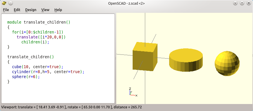
Three ways to chamfer,
but the right one is useless.
A manual drill (4/5), which handle you can print yourself.  Or, a more expensive reamer (1/5), that will suit many more sizes. Better get one long and thin one to have a very sharp angle and make almost non-conic holes. There are also bigger tools to chamfer holes (2/5), like the big one on the right. They are are useful, but you may want to check for 45° chamfer wood end mill, as they will use less space in the toolbox.

In any case, I think that manual tools let you do a much cleaner job compared to power tools when dealing with thermoplastics.


Of course, you will probably want also to have some taps (3/5) and corresponding drill bits. Now, most of the time it may be done with the help of a regular long screw and fast forward-reverse movements.


A set of good set of small files (3/5) are really useful. Some can be found very cheap on ebay, and still give good results as the ones below. They are very useful for printed joins when you need a tight tolerance.
Very useful tiny files. A round one and a flat ones are a must to post-process tight joins.


Assembling, mechanical tools and 3D printer maintenance


Small and useful multi-tool wrench. It cuts Nylon safely.
Not comfortable in my hand though.
A tiny pair of pliers (3/5) is a must have, and it helps also to snap or cut filaments more easily than anything else (think about Nylon: you cannot break it, and using a scalpel is out of question imho).


A set of hex keys (M8 is used in many printers, mostly because of the filament driver bolt). Actually a tiny adujstable wrench (2/5) would be very useful to replace a bunch of 8, 10, 12 flat wrenches, but I did not get anyone good enough so far (crappy sloppy ones from ebay).


M3 everyday tools. Well, the nut holder on top is bulky even
though I shortened it, I often use my nut calumet instead.
A high quality set of hex screwdriver (5/5). Actually, I better recommend a multitool that can hide long bits within the handle, so it takes less place in the box and has more than one size.


Pulley allen hex key (5/5), that are rarely used but that are compulsory to secure your pulleys on the axis.


My nut calumet (4/5), as it helps tremendously on the UMO for the rod caps and the nuts within the stock hotend fan... As you can print it it costs nothing and takes no place for what it brings.
The top wrench was "widened" specifically for the heater block.
This way I can remove it without burning myself.
BTW, the small adjustable wrench is too bulky,
but the cheap ones I tried so far proved to be too cheap.


Light/liquid grease for the rods and bearings. Sewing machine oil (5/5) is the simplest and best oil for a 3D printer. Teflon sprays (2/5) are "cleaner" but they do not last enough in my opinion. Thick grease (3/5) is a bad idea, even though they may be used nicely for the Z axis (and only there, please!).
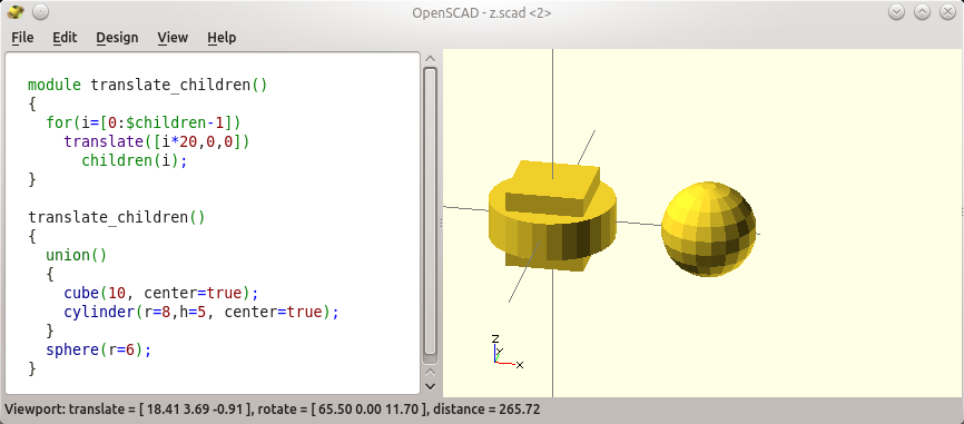

A very small flat screwdriver (?/5) will help you tune the tiny potentiometer on some Pololu drivers. Some people recommend ceramic (non-conductive) screwdrivers, but I find it works as well with a regular one. It may become a must only if you want to fiddle with the stepper power (e.g. to try and print faster).


Spare parts

Miscellaneous electric ties (4/5): small ones keep the electric cabling tidy, and large ones help routing the bigger cable and bowden tubes to the head. Some of them can be adjusted and re-opened, which is very convenient for the latter case. I always have some at hand. I often use scratch-like ties.

Spare gears (3/5) for the filament driver (though they they eventually break at the worst moment).

One more stepper driver (1/5) and RAMPS board (1/5) if you really want to make sure you can print when you want to print.

One power supply block (2/5), as it breaks more often than expected.

Some spare bowden tube (3/5), that I prefer in a larger diameter (see my post)

Obviously a proper set of spare nuts, washers, springs (4/5) for your printers. I also bought a comprehensive set of M3 stainless steel nuts to assemble my designs, as they are also the ones used to assemble the printer itself.
More tools and spare parts. I printed the small box for the set of screws, nuts and washer.
I usually also have a spare filament driver and almost one full hot end, but this is luxury.
The zip-ties and piece of nylon are very really useful though.


Conclusion

Not useful, but you always need to show what can be done (rod end, nylon hub)
It is tiny enough to be kept with the tools, so you always have it handy.


And always... I keep a carefully selected set of tiny but high quality printed samples (4/5) to brag about. In my case, my printer is probably enough as many parts were already re-designed.


The tool/dirt box (5/5) itself: it holds all the tools, and in my case it fits nicely the bottom of my Ultimaker, so it makes it very easy to drag around in only one piece (given that I also moved my power supply beneath the frame).


Also, I eventually bought some tools twice. Now I have one set specifically for my 3D printer work. I realized more than once that I had left THE required tool/fix at home just when I needed it badly on a trip with my printer to a friend or to a client. The worst was when I did not have the spring for the level of my filament feeder (I had to revert to electric ties... and it worked! At least I had electric ties).

A good set of tools really helps with 3D printers. Good tools help not only to fix problems more efficiently, but also to clean prints better than with the too common "basic" household stuff. What is nice is that the proper tool for the proper job is not necessarily expensive nowadays: most of these here were bought on ebay or at the local shop for a few bucks.


Nicely removing a Nylon object on a glued bed
with the help of a scalpel, equipped with a straight blade.


Headlines again... 3D printing guns, a passion?

$
0
0

Headlines again: 3D printing yet another part of a gun. So what?

Please Cody, yes, you the guy with big stainless-steel thermoplastic bollocks, please, now I want new stuff, like 3D printing bazookas, ammo or landmines!

I already tackled the subject it in this older post but telling that a 3D printer is probably not the best tool to use is not even my point here. Using a 3D printer to print more guns is no surprise, but I wish headlines focus more on noble usage like e-NABLE prosthetics. It is an excellent project, where volunteers 3D print free upper-limb prosthetics, like artificial hands for others. If your printer is idle, you should go and read about them!
E-NABLE: is this not a better use for 3D printing, according to you?
This way we have people printing tools that may harm people, while other people do repair them. Nice absurd world.

Here is my point for once: why do the words gun and freedom have to be put in the same sentence almost each time pro-gunners start to argue? What the heck?


Say, I never felt my freedom is harmed by the lack of firearms in the hands of citizens around me, including in my own hands. Europe has a long tradition on relying exclusively on the authorities to ensure both the freedom and protection of citizens. And any personal bypassing of the law is ... well, illegal.

But that is just my own opinion: guns are physically linked to violence, one way or another.

I expect better arguments from pro-gunners when they want me to change my mind!

Let me re-state it: why do zealots feel the urgent need to justify themselves and feel like I say that all gun owners are stupid? I only consider stupid the law that allows any one to own a gun and to carry it in public. I never said the opinions of others are wrong, and it includes those of gun owners or lovers. Now what happens at home is just personal business and a matter of education.

What really bugs me hard are the wrong arguments that are too often put forward. I like to argue, and I can be wrong, or fail to understand. But I need proofs, actual real statistics, science, sociology. No low-level bullshit motivated by some passion.

Education is harder than passion. Guts and feelings are just not enough (Calvin & Hobbes of course)
My biggest complaint are falsified arguments used to "counteract" gun-skeptics, or out-of-scope arguments like "cars are killing more". Hey, life kills at 100% rate - so what? By the way, even that argument seems to be wrong. Check, e.g. The Economist: "A gun is now more likely to kill you than a car is". Well... in the USA of course!

Most often people revert to individual cases where a gun would have "avoided" a problem (usually a shooting, how ironic!). It may be true indeed, but I believe in more scientific methods such as statistics. Individual counter-examples do not make the rule. They lead nowhere and sterilize the debate. Headlines are crap. Real studies rules.

Inductive reasoning is to make broad generalizations from specific observations, and it may be plain wrong: "Harold is a grandfather. Harold is bald. Therefore, all grandfathers are bald." (from livescience, a nice read on the scientific method).

But more than half of the population keep on using such individual statements to argue, never to try and get a bigger non-passionate picture.

See, when a raper is caught, nobody asks for all men to be sterilized! But that's as much as a scientific reasoning for me as the NRA saying that there should be armed guards in schools to shoot down armed students (i.e. "save lives"?). Actually, they would better close schools then, and bingo, 100% guaranteed no more homicide at school!

So? A weapon is a weapon. And a weapon adds surrouding danger.

Of course, there are fundamentally different views at play here. But once again, it did not say that shooting cans is not funny. And I can play paintball or laser quest games to fire at each other and have fun (I did).

But a real weapon is a real weapon. I would keep saying what I say, even for people that print knives with their 3D printer: not that interesting at best once done, and in any case dangerous when they they are carried in public. Who decides who may carry a gun? Who is the "good guy" and who is the "bad guy"? Seriously, if bad guys carry guns as much as good guys do, nothing gets solved, but "collateral damage" occurs invariably. Oh, what a funky name to say "innocent people deaths".

Is world is safer without guns in the public. I do think so, but...

As for me, I am still glad and I feel safer that no one but hunters own a gun here in France (and most of Europe). Unsurprisingly, the latter do account for so many "accidents" in the south of France, namely 16 deaths in 2014 (which is sounds so many, how stupid).

Technically and factually, a gun is a dangerous tool that allows any small kid or idiot to kill someone, and it happens just more often where guns are legal to carry in public, and to some extent also when owning a gun is made easy (see below for my moderation). A weapon may kill. No weapon cannot kill, period. More weapons around is more deaths, be it guns, knives or fists. The more you know there are many weapons around, the more you get nervous and you are prone to be aggressive with your own.

Carrying guns in public creates a risky social environment, to the point the police often fires and kills suspects and innocents way too easily and without solving anything in the long term. Compare to EU countries, like England where the police fired 3 rounds in 2012 (killing no-one). British citizens are around 100 times less likely to be shot by a police officer than Americans!

Sorry but I do not buy it when a two century old rule that initially was meant to allow citizens to protect the state against foreign "hostile" countries is now considered to be a private affair by so many.


Free education beats free guns!

Back to Europe: and still, Great Britain is even considered more dangerous than the northern European countries.

Anyhow, there are countries where it may be somehow easy to own a gun, but it is simply forbidden to carry it in public. Beside some psychopath who kills a lot once in a decade the average casualty is very small. Why? Because people are just well educated and laws prevent them from carrying guns everywhere (which in turn makes everyone want to carry one for self-defense: how ridiculous!).
Say, when Switzerland is probably ranked first for gun ownership because of their special constitution, there are only 5 deaths for 1M people, while there are 30 in the USA (check the stats here).

I was hoping that by the time we arrived here, we would have stopped trying to prevent things being banned, & moved to actually preventing people wanting to kill. You know, through being sensible and rational. But I guess I was wrong. - Nigel tolley in the original post.

Once again it all boils down to a better, good and free education for everyone in my opinion. It always works better than any gun or knife in the long term and even laws related to weapon ownership. A person who needs to fight to make his point is a psychopath to me, and gun owners are often tempted by the same kind of argument: better kill your neighbor before he kills you.
Sorry, I just feel better when the risk that anyone kills someone is simply negligible simply because there are no such weapons all everywhere. Just try peace for once, and it works better than casting war everywhere.

Now for sure, printing gun parts is going to be a lot more dangerous in countries were the remaining parts are readily available, or where you can buy ammo in a supermarket, and this is where laws are important. I feel glad to be in a place where it is illegal. Both the freedom and the safety it warranties for me each day is a joy :)

You can check and compare your country policy regarding firearms on this wikipedia page.
There I learnt that I could get a 5-year jail term in Germany just because I own a nunchaku. And I definitely would not have bet that Poland had the lowest rate of gun onwership in Europe!

Facts, not fiction nor passion. Do not get me wrong.

Article 0

$
0
0

Messy code, branches with a lack of guidelines and comments are killimg Marlin!

Marlin no more exists as a single, readable, common branch!

Where shall I go now?

In a previous post, I described a tiny contribution I made to the 3D printer firmware Marlin. The deal was to help with the calibration of a Delta printer thanks to a manual Z-probe (calibration really is the drawback of Delta printers, due to their weird geometry as compared to easier cartesian X-Y bots like the usual printers). It was already painful for such a small, one-time improvement to the code source, and given the invested time, I tried to make it broader by implementing multi-line comments (and to learn about git by the way).

This is how I feel when I want to code something in Marlin!
(Malcom in the Middle, fixing a light bulb)

So I worked in mainstream Marlin. My idea was that it could benefit to existing variants of Marlin as well, when they decide to get changes from the "official" parent. But it does not work so well in reality.

This experience unveiled another, deeper, issue related to the many Marlin variants, and I think it is due to the fundamental way github works, in addition to git own complexity. In my opinion, Marlin is just dying because of this, together with the limits of the Arduino platform.


In fact, shortly after my pull request was included, the basic support for Z-probes was removed from Marlin (the M700 - M702 gcode height probing commands were gone! -- I was there at the wrong time I guess).

May be it was changed in a way I could not find it anymore (I do not think so)... Or it was too experimental (since M7xx commands seem not to be well defined). Or someone removed it by mistake. Or it was considered too obsolete a procedure.

IMHO it is still straightforward to assess the height of three point by use of a removable push-button on a socket that is hand-placed below the nozzle at three points on the bed. Actually, I do not want to add complexity or to hack to my printer with retracting probes, nor to add weight to my head (even though there are interesting hacks of course).

Clever but complex retractable automatic Z-probe,
with multiple test points on a Delta (Johann Rocholl)

Anyhow here is the problem: unless I try and modify Marlin again so it stays compatible with my use of "discarded" G-code manual probing commands, I would have to change my hardware.

In my post you may have seen that any contribution to a project hosted on git hub requires a new branch to be created and a parent branch to be chosen.

This is where a bigger problem occurs in my opinion.

Down with Marlin (variants)?

First, do not get me wrong: Marlin is vital. Marlin was a huge step forward and it is still the most widely free and open source software for driving low cost 3D printers. I do use it on all of my three 3D printers.

But in my opinion, Marlin no more exists as a single, readable, common branch. And it may be doomed.

First, it is already bloated by so many different electronics and hardware setup that it is barely readable. It looks like Marlin death is slowly approaching because of the new hardware it tries to support further.

Then and thus, there are myriads of branches, including some that are alive and made by well-know pillars of 3D printing, such as Richard Horne (see this branch tweaked for his 3DR v2 Delta printer), or the older deltabot branch by Johann Rocholl (arguably a father of most Delta printers). Sure, Ultimaker sponsored Erik Zalm when he took over Sprinter. This gave evidence about the main branch, which is a beacon in the whole mess but which is not enough sadly.

Indeed, the main branch no more looks like a definitive reference for wilder children or hardware configurations. There are tons of variants, and I am not even speaking of older variations on older branches like Sprinter, nor the parallel rise of other firmware (which may be the only possible outcome in the long term). This really is not the fault of the tool, but it helps spreading the disease by not requiring developers to stick to correct guidelines (like, please: comments and minimal documentation on what to find where and why).

Even very knowledgeable people like Anthony Morris (aka ThantiK) ask for help about which Marlin variant to use for a specific hardware, and there is no clear answer. Or it sounds like "better make the hardware according to the firmware you chose".

I cannot make my mind either about the branch to use, which is live, which is stable, which I can trust, which I shall contribute to, which suits my need... And this is even more of a serious problem when features are dropped without notice from the main branch!

My options right now...

1) I would love to keep on using the mainline, and even to adapt my own needs or even my hardware so it reflects what Marlin supports nowadays (unhappy though). Since M700 are gone and I did not want to make my hardware more complex, I had to revert to manual M206 to set the offsets on the origins. But this is unbearable (I have to "send" the g-code with guessed values with an external software like pronterface: back to prehistory! I hate tethered printers).
I definitely could write some more software to fix my burden in main Marlin, but I am not sure I can be confident that Marlin will still be compatible with my hardware in a few releases, which kills my motivation to contribute to it (especially due to git + github tiring procedures imho). And would I like to spend half and hours and days of reviews to have my specific need included in next Marlin?

2) So I could just stop trying, and live on my own branch, as many do. Then I could try to contribute to mainline on regular occasions. It is probably the common strategy among many developers. But it is a pity as I would just create one more pseudo-active branch, and it would eventually divert so much from mainline with time that it will no more be possible to merge the two (as I do not intend to work a lot on it, not even to keep it up to date with the upstream). There are just so many dead branches of Marlin already on github that adding one is not wise.

3) Or I can use my own Marlin branch and stop worrying at all about other hardware and other branches. Trying to support all hardware in a single branch is cool, but time proved nonetheless that it resulted in many wild forks that defeated the intention!

4) Further, I could even get rid of all existing support for the hardware I do not own! I considered this nasty until I thought about how more productive I would be with a clean source to work with! There are just too many #defines in the existing configuration.h, for hundreds of variants of hardware, that it is unreadable and very tricky to submit anything safely back to the main branch anyway.

5) I could give other firmware a try, like Repetier. But it means dropping all help I could provide to the main community. And it does not solve another raising issue: the RAMPS electronic environment is so much limited by the tiny Arduino Mega that I consider it to be at the end of its life...

6) So... I may better forget about Marlin and Arduino alike! May be it is time to have a clean start with Smoothieware on my old but powerful R2C2 ARM board instead (32 bits, 100MHz). This would be a big change, but a larger environment and a faster CPU would give real room for real improvements. It could also be a chance to get rid of most of the mess at the source code.


The Arduino is dying as a 3D printer firmware controller. ARM is the future!


Switching to ARM is a good thing, and more people are considering the move to be the next major step in 3D printing (see Thomas Sanladerer's review of the Smoothieboard for example). It gives some air for improvements, and I hope it is well written as a new start. In my opinion, a recent firmware would benefit a lot by relying on an object-oriented paradigm and on hardware abstraction layers via compulsory interfaces, pure virtual methods, etc.

Most 3D printer firmware for ARM processors are still based on the original GRBL G-code interpreter, just like Marlin is. I will have to look at the source code of GRBL also, it seems ubiquitous! I did not look at the source code of any new firmware yet, but I sincerely hope they ensure that any subsequent software development does comply with real and safe standards, contrary to Marlin which is full of ugly tricks and unsafe shortcuts (OK, they might have been considered compulsory because of the limited power of the Arduino, the Arduino IDE, and the anarchy induced by github imho!).

And still, I find it hard to conclude I should better move to an ARM board! It requires some physical and hardware changes to my existing printer. My goal was only to try and improve the calibration procedure for my current Marlin / RAMPS setup. What a pity!

I just cannot make my mind... Someone should write a post with the different branches, their activity, state and compatibility.

(Uplate to make it clear that my rant is not against github really, but just a point of view on the state of Marlin - and I praise applaud the evelopers that have the energy to contribute to it regularly! )

"It is better for your safety that we are opaque" (Volkswagate)

$
0
0


"It is better for your safety that we are opaque"

I just read an article on the BBC related to Volkswagen and the "(...) argument for stopping people fiddling with those systems, because if you don't know what you are doing - or even worse do know and have malicious intent - you could create genuine safety issues."
Volkswagen in 1969 by John Muir
But are we still complete idiots?
This post not only relate to Volkswagen, but to any big company using proprietary stuff and saying it is good for you. You can replace "car" with any non-open piece of software or hardware alike. Transparency is just so hard to depreciate, especially when you are talking to your own customers.

Here we go: "If we give access to our source code, our cars will risk more hacking".

Yes and no. Manufacturers just fail to understand that their cars will eventually be hacked, be it open or not.
Actually it already happened (e.g. some fatal hacks). Hackers need no source code. There are thousands of people that will try to reverse-engineer their protocols, soon or later.

Security through obscurity is a business fallacy.
Is Linux more often hacked than windows? Yes, obviously. Now is it less secure? Certainly not. This is simply the consequence of two strategies regarding openess and transparency. The car makers are no software makers: they say closeness is necessary for the user security. I am sure that even Microsoft no more says that (funny one: "Open source, from Microsoft with love" on github!).

Moreover, their fear of security-related hacks is revealing for me: it is fueled by their lack of confidence in their own capabilities to secure their cars and their software. This is exactly where third party experts should be in, and this is what they refuse to do, citing... security reasons?!

Many sensitive software are open sourced. Actually they are enough secure that the vast majority of the worldwide internet is heavily relying on open sourced components (linux, apache, mysql, php to name a few).

By the way, their stance denies the possibility that someone fixes their mistake for free and for the benefit of everyone, including them. And when they try to fix flaws, they do not always do it properly either (Jeep sent USB sticks via the postman, giving even more food and means to hackers).

So when the source code is not available, they should do a better job at protecting their cars at the very minimum. We are now driving computers which requires essential firmware updates. But car manufacturers are like the vast majority of the industrial companies that are switching to the "internet of things": they do not seem to consider software security before they release their software. And here, the "computer" can kill you!

Again: "if we open the source code, someone who tampers with it may crash his car"

So what? Come on, that would be a problem for the user himself, and for third-party controllers if any. Who would sue Microsoft because his pirated version of Windows crashed his hard drive?! Who ever installs Cyanogen Mod on a phone makes the manufacturer not responsible of any quirk that happens to the phone.


You just need to know that you may void the warranty of your product in doing so. They genuinely can say they cannot be held responsible when your firmware does not come from them! Do they really think they would be held liable in justice by someone who hacked his airbag and who ends in a tree? Or while texting?

And if/when a user installs unconfirmed third-party car firmware, *he* is the one to blame when something goes wrong with it. Think about getting a trojan by downloading some dubious freeware!

Just comply by the law. This is not their business!

What they fail to see is that tampering with the car firmware still means that you have to comply to the law. Not doing so means a big fine when you are discovered. And it is not necessarily the car manufacturer business to check if you stick by the law. This is the job of other people, and controls can be preventive or post-mortem (according to the state policy -- another topic).

Comply with the law! - Dilbert
Actually people are already hacking their hardware. Some mount unsuitable tires, while other just pour the wrong gas in the engine! Do they complain to the manufacturer?

The car manufacturers could just tell "here are the only firmwares we certify" and use real digital certificates on it. And if they really were willing to cooperate they could embed pieces of codes from third parties in their own releases. They could even pay hackers for discovering security flaws, as more and more companies do in the software industry.

Now, well, they tell us it would be illegal to hack their firmware, while they are illegally hacking it in the first place to circumvent the laws, how cynical!

The funnier is that they ask that we trust them ... for our own security!

Seriously?! Hey they just cheated on everyone for years, without much regard to our health (nor to the highly regarded reputation of German manufacturing). What for? Raw, stupid short-term profit. What I do think is they would have sold us cardboard boxes if it was legal.

This is the time when *they* should be transparent and try to repair the incredible damage they have done consciously. No, instead they keep asking for confidence without letting any one see the inside?

Speaking of transparency... they could get insight from Henry J. Heinz that made the first transparent tomato ketchup bottles, and who helped making the first health laws and quality controls a reality... while helping his own business! Yes, car manufacturers could learn from century-old tomato ketchup producers, check it here: Concerned citizen or clever capitalism? But they try to escape the law, instead of using it for a better business.

Double speech, public relations, marketing and bullshit again.

This is just double speech, while they are in an inexcusable situation. It reminds me of Monsanto that was arguing that their GMO seeds are sterile because of safety reasons while they were saying they were totally safe at the same time. 

Security through obscurity is insufficient, and naïve at best. And security through minority is not available when you sell millions of cars. 


Hey I better go and check that my old Transporter isn't made of cardboard actually. At least there is almost no electronics in it.

Preliminary expectations and design options for a prosumer, fully opensource 3D printer. Your opinion matters!

$
0
0

Call for feedback: designing an opensource, prosumer-grade 3D printer

We are currently designing a 3D printer for advanced, serious, or professional usage.

The main target is reliability. The price tag is secondary, but we expect it to be $3 to 5K. Would you help us with this short survey? Being open source, the preferences of the community is very valuable to us, and we think it may be a win-win strategy.

Please feel free to share the link, every opinion counts: https://jeremiefrancois.typeform.com/to/xbuY9S


Sensors and issues for automatic bed leveling and height adjustment

$
0
0
My printer eventually has a fully automatic and hardware bed leveling (aka tramming), and bed height (aka Z-offset). Yes, it now handles any tool height without any user action, in addition to a long-wished automatic leveling of the bed.
This is part of preliminary studies for a prosumer open-source printer, for which you are more than welcome to give your opinion! The entire bed structure was entirely revamped, as one important point in my former wish list.
Revised heated bed with automatic tramming and tool height compensation.
Since I wanted to document both the new bed but also why I wanted it this way, this first post addresses usual sensors and strategies used to deal with the bed calibration. The deal is to make a bed level and to start printing at a proper height, and there are many ways to do so, but not as conveniently as I wanted (which will be documented in a subsequent post). The second post will show more precisely what and how I did it.


3D printers need a fine, flat, level bed... or they fail.

A precise bed level is just plain compulsory. As listed in the corresponding section in reprap.org, a wrong bed leveling may result in
  • The initial layer is not sticking to the bed.
  • The initial layer isn't complete; parts of the print just don't get laid down.
  • The head scrapes the bed in some spots (you probably worked this one out for yourself).
  • Plastic gathers around the head during printing of the first or second layer.
  • When printing the second layer the print head is picking up the first layer
There is no hope to print properly with a skewed surface. Not only the first deposited layer must be parallel to the bed surface, but it must also be squashed "just enough" to keep the part stuck on the bed for the duration of the print. Also, the initial layer height must be known precisely for the correct amount of plastic to be deposited (most of us guess the value -- a safe bet with experience).

Side note: other factors may pop the initial layer off the bed. Most thermoplastics contract when they cool down. Old-school Polycarbonate is hellish in this respect, when ABS and Nylon can be difficult. You need both a bed which is well-calibrated and heated, and often use additional glue or special material to keep the deposited plastic stuck on the bed for the duration of the print.

The problem with bed tramming

Manual bed tramming is time consuming at best, and difficult at worst. Most of us often overlook the calibration, by considering it was done weeks or month ago and it did not change... But not all printers are equal here. For example, I probably can drag my sturdy printer here and there without trouble, when most of the entry-level repraps do require a calibration again.

A tutorial on bed leveling by Tomas Sanladerer
(his channel is full of such wise videos)

A rule of thumb is that cheaper printers need more regular maintenance, even though some get software compensation nowadays. The reciprocal is not always true, though.

Anyhow, bed leveling is just not something that can be overlooked to get easy and nice prints. And probably all printers need to be calibrated regularly, soon or later, manually or automatically.

Another fundamental issue is that each time you change something to the head or to the nozzle, a new "zero bed height" must be set. This value is the initial bed distance, not the bed level. A large unwanted offset may kill your plate or your gantry when the nozzle crashes into the bed during homing, but tiny difference as small as 0.1 mm are often enough enough to degrade significantly a print. The latter happens when your new nozzle height changed just because tiny bits of plastic were left in the thread, or because it was not tightened to the exact same force as the former.

Now, obviously, when you change the complete head, a new bed height has to be set, even though the bed leveling should still be OK -- the bed height is not.

All in all, the difficulty to properly calibrate them, and keep them calibrated is a major reason why printers are not as mainstream as the hype likes to tell.

Common bed leveling mechanisms

You may want to skip this small state of the art if you already know this, before I talk about my implementation.

Historically, beds were first adjusted manually via screws and springs: the user moves the head over the bed at different places, check the gap and tune the screw so that the nozzle almost touches the bed. The goal is to leave a few tenths of millimeters. One classic trick is to sliding a sheet of paper between the two. Note that leaving any gap is arguable, but I understand that nobody wants the zero to be a real contact for security reasons. Leaving a safe tiny gap ensures that the nozzle never gets dragged on the bed accidentally. I do it also, but then the gap which is left must be taken into account for the first layer thickness in the object slicer. It would be better that the slicers sets this value, and not that we set the value in the slicer... Anyway.

First, better use a flat/planar bed!

I made an assumption here. I consider my bed to be a perfect flat, and this is mostly why I am using a glass on top of an aluminum bed. Having a perfectly flat bed is important, as nothing else than a complete probing may compensate a bent or a deformed beds. Given many height values, the firmware can compute and correct the 3D model in real time, so as to compensate for the surface irregularities -- we will see that again later.

As a side note, delta printers are beasts of their own: since the gantry provide no natural movement in the X-Y plane, a multi-point calibration is often required (check it with Marcus Littwin -- the author of Repetier, a slicer and firmware).

Manual bed leveling.

Bed flatness and bed leveling are two different things. You may have a flat bed (aka. a plane), but it may not be parallel to the X-Y movement of your head, which is our main subject here. Historically, bed leveling was done via a few mechanical systems.
  • 4 manual screws pull the bed down, and springs pushes it up. For example, the original Ultimaker had such a 4-point bed leveling , and I still see new printers arriving on the market with this very wrong design. Hey, a plane is well defined by 3 points, not 4! In fact, the fourth screw will always go against the 3 others... and in the worst case, you may even bend your bed surface if it is elastic enough (and then, no way you can print correctly).
  • 3 manual screws: this is the minimum you ought to have on a "modern" printer. And indeed, it is the most common system to level a bed. Actually, it may also be enough if your hardware is sturdy (or even expensive), or when the printer is not dragged here and there, when it is not subject to highly variable temperatures, and when your tool set does not change.
My former heated bed used a central elastic pivot point (made of half a squash ball), where
the front pair of screws pulled the bed downwards while the third one is fixed (not seen).
  • A smart semi-automatic bed leveling was made for the Kuehling & Kuehling printer. In this design, the nozzle pushes the bed down to compress the springs to a known height, and only then thumbscrews are used to lock the height (note that the thumbscrews could be activated automatically themselves).
  • A similar idea was done by Scottbee and featured in hackaday, as a fully automated system. Sadly, I did not hear much about this system. But the idea is there.

Automatic and semi automatic bed leveling

Next came printers with heads equipped with a sensor to record (aka to "probe") the bed by moving closer enough so the sensor triggers.
Contact probing and flatness compensation on a delta printer
by the legendary Johann Rocholl, on his mini Kossel

  • Contact probes were first tested, where a microswitch or an infrared barrier is indirectly activated when the probe gets in contact with the bed. The problem is that either the probe or the nozzle must be in contact with the bed, and not both for obvious reasons. Hence, a servo motor or a a solenoid, is often used to deploy and retract the sensor, so that it protrudes below the nozzle during the calibration.
By knowing the "constant" difference in height between the probe and the nozzle (so called "Z offset"), the firmware knows how far and unlevel the bed it. The tricky part here is "constant", which may not be so constant as we will see in a minute.
  • Contact-less probes are often better, not only because they no more require a heavy, complex and often unreliable mechanical deployment system, but also because they are immune to wear (like infra-red diodes or hall-effect sensors), or even to dirt (like inductive sensor, as commonly used on dirty CNC machines). They are also lighter than contact probes and need less cabling (no need to move the probe in and out of the way).
Contact-less inductive sensor: a howto and an example.

However, inductive sensors require a close metallic bed to trigger and they may be subject to electromagnetic noise. Infrared or hall effect sensors precision is often poor: the triggering distance is not reliable enough. This also depends on the price and sensor you can afford of course.

Note: many if not all firmwares already support probing, with or without automatic retraction. In case of Marlin you have to tweak the configuration somehow and recompile the firmware, which may get tricky (just to get the correct branch...). More advanced features are also supported such as the "matrix probing" (probing is done in many poinst so as to correct non-planar beds -- which proves to be extremely useful for Delta printers when their arms are not perfectly identical).

Now, probes that are attached to the head will add weight to the head. This is detrimental to speed or quality as more inertia is more trouble. Even fixed probes like inductive sensors are often bulky: they may reduce the number of objects that can be printed serially on a bed, since the head need to move around formerly printed parts without knocking them down.

Z-offset: an issue with the usual bed leveling systems

A professional tool changer (ref.).
See how no tool ends at the same height?
In any case, two problems remain with the above systems. Even when the bed is level, two other factor may impact the print.

  • heat expansion: when the bed heats, it often expands a bit vertically, especially when it embeds an aluminum plate (which I would recommend to homogenize the heat). Without a sensor, most existing systems will not take this into account, so they better be set after the bed is hot.
  • reciprocally, helping calibrate the tool height is something almost always forgotten in the 3D printer world as for now! But the distance to the bed also changes each time a nozzle or a complete head is changed (possibly for dual heads, but also for manual head changes). Each tool has its own "Z offset".

A remark on dual head setups

The excellent BCN3D dual head setup I discovered as
a moderator at the 3D Print Show Paris 2015
All in all, manual alignment of the heads is both difficult and extremely non user-friendly, to a point it took years for printer manufacturers to propose reliable dual head systems. In fact even single-headed printers require regular re-calibration, possibly each week or month at best as said by the Kuehling brothers (and even though their printers are really good pieces of engineering -- not low cost repraps).

Back to dual heads: say, if the nozzles are not exactly aligned, or if one oozes a bit before it cools down, then it will kick the part being printed by the other nozzle. Vertical alignment of the nozzle outputs must be achieved to less than a thenth of millimeter. Manually, it is almost impossible without some help from the design itself (e.g. sliding the entire barrel up and down in an Ultimaker or in a Kraken is quite hard).

Designers now often dissociate the heads to reduce the problem drastically, as shown above in the BCN3D printer for example. But the head nozzles still need extremely careful vertical adjustment, just as with more or less usual multi-nozzle hot ends.
The Kraken by E3D. Four hot ends to align perfectly!

In deeper trouble now: forthcoming tool changers!

Automatic tool changers are devices that let the machine change its tool without any user action, most often within the job.

Some high-level CNC milling machines featured tool changers for years already. The need was high for these, because a single work session requires many different tools (e.g. milling a path on a PCB with a V-bit, then drilling the holes with different diameters).

But nowadays, the need to 3D print with different material is also becoming important, and soon compulsory. So 3D printers will soon requires tool changers aswell.

A very few people already tackled the subject. Most notably to me, the prolific Markus Seidt (aka wokbrenner or foehnsturm) did this oustanding combined printer/polishing machine:

An outstanding automatic tool changer for an Ultimaker by Markus Seidt.
This is one of the earliest designs for a 3D printer and it relies on magnets.

The so-called tool "Z-offset" is most probably computed once, manually, and then given to the machine so it adapts the height according to the tool in use. It is somehow easier when the tools are the same as above, and when the tool holder grabs the heads is a very repeatable way.

Bed adjustments with sensors on the bed.

The other major option is not to carry the sensor on the head, but to keep it in on the bed. This results in less visible/moving cabling, and less weight to carry (both are a good thing).

On CNC milling machines, a contact switch is usually placed on the bed, and the head is then lowered until it touches the probe. Often electric conductivity is used for a very high precision (check this small instructable for example, or see the video below).

Zeroing a CNC with a probe (and and electric contact)

But these are still all manual operations: forgetting them, or failing to do it properly will break the bits and ruin the work. The damage is lower on a 3D printer compared to a CNC mill, but it still means failed prints and wasted time, and angry users.

Zeroing a CNC is often achieved by sensing an electric contact. On a 3D printer though, the milling bit, the printer nozzle, or the bed itself may not be conductive -- or more exactly no electric path can be made from the nozzle back to the bed. The electic contact probe could be made with a reliable microswitch, but it would gather dust, oozed plastic, and it will be a problem very quickly if it is left in place.

Automatic bed leveling with permanent sensors inside the bed

Manual procedures may help with automatic tool changer only when each of the tools are pre-calibrated and the mechanical tool holder is very repeatable (and better not mix the toolset).

Finally, locking a tool in place is hard to achieve without tiny and non-repeatable errors, which in turn leads to irregular heights or lack of precision. On CNC mills, it is probably even impossible to adjust the drill bits properly as the smaller ones can be swallowed completely in the collet chuck.

No... the real deal would be to detect the exact time when any tool that gets lowered gets in contact with the bed, because we would not only be able to tram the bed nicely, but also to compute the proper Z offset for the tool.

We have seen that relying on electric contact of the nozzle on the bed is possible only with bare aluminum beds and conductive hot ends. Moreover, a 3D printer heating cartridge is often driven with PWM, which generates a lot of electric noise and may pollute an electric signal.

And anyhow, our bed may be coated or covered with a glass plate, so it is not conductive. Period.

So far, I have never seen someone using retractile sensors on the bed itself, where a servo motor would slide or pop sensors in the corner of the bed for the head to go a touch them. I guess it would be much too complex to get something reliable (and I am not even considering the complexity).

Could we sacrifice a small surface of the bed, with protruding sensors? Why not... but it gets impractical as soon as the bed can be removed (a desirable feature). And the sensors probably get exposed too much, especially with a heated nozzle moving around.

Or again, may be the head could move out of the bed to probe a fixed sensor (only to compute the tool height). But sacrificing any part of the printable surface for calibration is a pity.

So... could sensors be embedded in the bed, or under the bed instead?

Yes. And there are different options, like having a magnetic field sensor under the bed, and a magnet glued close to the nozzle. Now, for the same reasons as above, I tend to favor mechanical contacts over distant field sensors, as the formers leave no fuzziness on the measure.

So what kind of sensors? The most interesting to me are pressure-sensitive ones. They can "feel" when the nozzle enters in contact with the bed, i.e. when it starts pushing it down. Of course the sensor need to be fast to react, and sensitive enough to get the signal before the nozzle breaks anything...

Sensitive load cells may be an option, even though their signal is more complex to analyse and they require amplification and proper calibration. For bed leveling, most of the load cells are also probably unsuitable because of their weight range. Still, Airtripper, as an another and early hacker god, used some to experiment with filament force sensors

So far and in my opinion, one of the most promising kind of sensors are FSR: Force Sensitive Resistors. As they name suggests, they are resistors that change with the applied pressure. Their main drawback is their price, unless you make them by yourself (easy, but I suspect the foam may wear out quickly as it is not intended to be squashed repeatedly contrary to FSRs).
And... without much surprise, a few people already tried FSR to help with the bed calibration on a 3D printer. The video below shows them used on a delta printer. The FSR are the 3 round sensors placed just below the glass plate.

Unsurprinsingly, Johan Kossel again:
bed calibration using force sensitive resistors.


FSR are also what we used, and the complete setup will be documented in depth in the second part of this post.

Conclusion

Bed tramming and tool height detection... lots of options, eh?

But in any case, I am sure that automatic probing will soon become a must for user-friendly machines (for 3D printers as much as for CNC mills).

As for now there are four main options:
  • tram the bed manually, with springs and screws
  • probe a static bed and compensate with the software (deform the printed object accordingly)
  • design an extremely sturdy printer that need only calibration once before it is sold (costly)
  • automatically tram the bed with help of an automatic probing, and 3 actuators
Only the last option solves both problems at once, which is very important as soon as the printer's heads can be changed. And 3D printers with tool changers are a near and very expected future in my opinion.
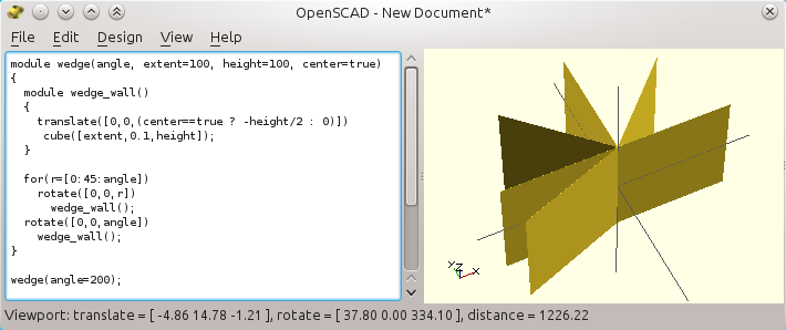
Time to switch to my own bed ;)

A Force Sensing Resistor (FSR) on a hidden plate in the bed. Its resistance varies with pressure.
It is used here for an automatic 3D printer bed leveling system (and, yes, my plate is rusty).


Tribed: a fully automatic bed leveling and tool height adjustment, with FSR and 3 Z screws

$
0
0
This post is the continuation of my preliminary analysis regarding bed tramming and automatic tool height adjustment. So far I never made the step to redo my bed, even though it was on my wish list for years. Now it is a reality :)

Early testing of the complete setup : starting with a properly calibrated bed,
corrupting it manually, and letting the system auto-calibrate it again.

So why now? A few months ago, someone came and talked to me about his wish to design a new, open source, user-friendly printer for the prosumer market. Please check this as your opinion counts!

All in all, it was an excellent reason to realize my idea of a fully automatic bed leveling. And since the new printer will also be opensource, here is the work, design and my analysis. How nice: not only I was given the possibility, but I was asked to do so!

As said, this improvement is part of a longer effort towards a user-friendly printer, for more reliability and less manual tweaking. My Ultimaker itself may eventually be ditched one day. Huh. No, I am joking. Well.. unless the new one is really is obviously better... Damn, that's exactly what it is all about :/


Automatic bed leveling and tool height compensation

Specifically, the idea is to combine bed leveling (aka tramming), and tool Z offset (automatic calibration of the tool height). The latter is important as we plan to offer multiple heads and an automatic tool changer (my next work). Nobody wants to deal with the corresponding offsets that needs to be set to less than a tenth of millimeter to avoid havoc. You can read my preliminary analysis there, but here are the main goals for the combined bed leveling + tool height calibration system:

  • automatic bed tramming - bed should be level after calibration, with no user interaction
  • automatic Z offset calibration - i.e. according to the mounted tool (various length)
  • repeatability - two successive calibrations should give the same result.
  • real accuracy - vs. software compensation of imperfect bed calibration
  • simplicity - reduce mechanical risks due to wear or backlash
  • compatibility with heated bed and 3D printer designs whenever possible

Secondary, but nonetheless important items are:
  • small weight - less inertia for better speeds and overall print quality
  • small footprint - reduce impact on the printable volume and surface
  • minimal cabling - mostly, tools should not carry duplicated sensors
  • steadiness of the bed - no bed vibration including at high speed (springs?)
  • low impact on the firmware
Given prior analysis, I settled on a fully revised heated platform, with 3 embedded FSR force sensitive sensors, 3 independent Z screws, and some modified software.

Interesting (temporary?) options left out

The tiny low cost 15mm linear actuators
I'd use if I had to tram a cantilever bed.
Using a regular cantilever bed with 2 small-range actuators could do the job. But I tend to dislike such "hanging beds" as they eventually wear out and leave room for vertical free play. Well, unless the whole thing is supersized (which, in this case is not really over-engineering, but just pricey).


For example, the bed of my old Ultimaker could be shaken vertically by a few millimeters at the end, and I was never able to fix that with the existing design. For some time I thought about adding a second slave Z screw on the front side just to prevent this sloppiness. Better add another one and fully control the 3 "corners" of the bed.


Rediscovering what is done already: FSR groove mount by edlep.
I would try to use a load cell instead, for a sturdier mechanical
attachment (but heavy and more complex to interface).
For some time I thought about putting the pressure sensors on the tool holder itself. The head itself would then know when it hits the bed.

Three-point bed attachments would still be required for the actual tramming, and a cable to be run from the tool holder to the firmware.
This idea is not yet fully out of my mind because it is elegant, and it may be even more reliable than embedded sensors in the bed. And I found someone who did it, so it may not be stupid ;)


Still, I first want to check my current solution. I suspect that the mechanical joint at the head may then be somehow fragile with FSR that cannot be squeezed too much (some floating must be left, necessarily). It may create vibrations during high speed printing or milling for example. In this regard, a metallic load cell could be a better choice than FSR, but it is sensibly heavier also and more complex to interface due to its wheatstone bridge.

Now for regular single head printers, I really like the idea: it is both simple and probably efficient, so go with it and tell me ;)

Hardware choices and requirements

Overall the improvement required significant additional hardware:
  • of course, three FSR sensors and a new bed gantry...

    An FSR sensor on the bottom plate of the bed (the tail goes below the bed).
    The corresponding nut is linked to the plate with a 3D printed join,
    aluminum tube towards the other links (in a triangular setup),
    and glued to the bottom of the bed with high temperature silicone.
  • due to the two additional steppers, I added a 3 axis CNC shield slave (running a firmware of my own, not GRBL). There are now 3 of them for Z in place of a single one one.
  • so... 3 Z screws instead of one. By laziness, I bought Nema17 steppers pre-equipped with Z screws (just to test initially). At least there is no more Z elasticity as with those common aluminum couplers (oldham are better but not cheap), and the screws were still straight enough for no noticeable wobble. I used the worst one for the background center "free" screw.
    Basic all-in one stepper motors with lead screw (surprisingly good)
    At least I avoid low quality aluminum flex shaft couplers!
  • a few easily designed and 3D-printed holders for the top front roller bearings, and two for the bottom steppers. I should relocate them under the bottom plate of the printer as done the third stepper (I re-used the existing holes of my Ultimaker original). The top of the screw of this stepper is left "free" so as to to over-constrain the 3 Z screws (this is a common error when people want to constrain everything. The front two screws are already doing the job nicely).

    Bottom and top 3D-printed parts. Both are temporary, since the stepper should
    eventually be relocated under the wooden bottom (like the regular Ultimaker Z),
    and the top part should not protrude like this. No printable area is lost,
    as my banana block is already hitting the end stop in this configuration.
    • you may have noticed the small arduino pro mini on the bottom of the printer. It is dedicated to the FSR filtering, so that they behave as regular hardware end stops for the CNC slave. Initially I wanted to make sure they acted reliably and independently of the main controllers, but timings seem to indicate it could be computed by the slave or even the main board for less hardware.

    Tricky points

    Time will tell but I know that both guiding and driving with a lead screw is somehow "impolite" to most engineers -- but I am pragmatic: it seems to work quite well with only three Z screws that do both jobs. The bed does not move at all. Milling may add lateral wear to the nuts though, but we have here very cheap Chinese stuff so they can be improved also.

    Wear. This is yet to test... For this reason, part of this post may then get updated without much notice, and as usual, any feedback is welcome, so feel free to criticize!

    A major trouble came with how to insert and fix the 3 pressure sensors to the bed, without impacting the surface area, without exposing them directly to heat (the bed shall be able to go up to 150°C), and more importantly.

    These show how sensitive the FSR force-senstive-resistors can be, after heavy filtering.
    I did not keep this seemingly fine setting though, as it generates too many "false positive" signals.
    So I had to ask for more pressure before they trigger. Some room for improvement is left !

    More importantly even, I had troube figuring out how not to overload the sensors because of the bed weight (PCB heater + aluminum plate + glass plate). Resting the bed directly on the FSR transmitted also all kind of vibrations which triggered them too easily unless I asked for excessive/risky pressure (the nozzle could break the glass, no good).

    My best idea was to use neoprene, that protrude largely around the FSR sensors. This way the bed is well maintained laterally, it will not transmit its heat to the FSR, its weight is well supported, but it still transmits very well the slightest pressures. And neoprene does not melt like thermoplastics (I would not recommend to print these parts!).

    Neoprene is just excellent as a heat-resistant spacer, as a shock absorber,
    and as a weight relief. It filters most of the mechanical noise, but it transmits
    nicely the pressure from the nozzle on the top plate to the FSR.
    Electrically, using the convenient internal 10K pull-ups of the Pro mini was not wise, as it sent the signals in a tiny dynamic range, which was prone to trigger false positive. I had to use external resistors (not difficult but it means specific electronics...). False positives are when the sensor triggers abusively (e.g. when the bed brakes hardly while it goes down, due to interia). They just ruins the very first idea of user-friendliness!

    Also, the CNC slave is used to drive 3 stepper drivers. All in all we have 1 X, 1 Y, 3 Z screws and 1 for each extruder. With our minimum of two heads by default, it means 7 steppers and most 3D printer boards cannot handle so many motors. As long as we do not design our own electronics, which we may better do in the end, we had to use a slave controller, and this sucks. The good news is that it only controls the Z during calibration (see below my trick with "transparent mode").

    Software requirements

    There were also some software modifications:
    • I modified Marlin to activate the third Arduino Mega serial port 3 (soldered a connector on the board). It links to the CNC shield slave (on an arduino Uno). I wrote a small protocol to control the slave from Marlin, and I added corresponding custom menus in the LCD too.
    • I wrote a basic but fully custom stepper driver for the CNC shield, named "bunchosteps". It should not have been compulsory as GRBL is a very nice piece of software and does its job. The problem is that it was made with "only" CNC control in mind, notably with the "fatal" endstops and asynchronous operations and look ahead (block-based segmentation of the commands). It took me too much time to tailor it to my needs so I rewrote my own simpler version. It is also low-level (non-Arduino) code, based on fast interrupts so as to achieve fully controllable smooth Z movements with acceleration and brake (you'll see the effet in the introductory video), but it also handle direct interrupts, common 3Z movement, and most of the calibration (complex interaction with the pseudo-endstops), thanks to a pseudo g-code interpreter fed via the serial link. For me it was much simpler to write one from scratch and deal with it overall.
    The sources are posted on my github account, but they are mostly proofs of concepts, still in evolution. So better ask me before you clone or you fork them, and use with care! I need to polish the FSR filtering, but I see Johann Roscholl already has posted such source code also (check the page! I realize a lot work was done there already).

    I should at least post the low-level Serial3 support for Marlin as it may help others. I still am unsure whether I rewrote something existing, but I really was not able to active it in the existing state of Marlin.

    How it works

    Bed leveling

    Tramming is triggered by a specific "tribed" menu.

    The bed components.
    It is a mix of XY moves (done by the master), and Z1,2,3 and combined Z (done by the slave). The procedure is simple : lower the bed (to avoid crashing in it), do a regular XY calibration (find origin), move back to center, home the entire bed (to have an average point of reference). Lower again slightly (assuming the bed is not skewed more than this value), then move sequentially over each of the FSR sensors, raise the entire bed until it triggers the sensor. Lower the bed again, but only by a few millimeters, then raise only the corresponding Z to "home" the axis (this is where the calibration really occurs). Rinse and repeat.

    The origin of the first axis is not changed, as it is used a the unique reference. Only the second and third axes are modified to that eventually the zero matches expectation.

    As usual any homing is done in two passes: a fast seek up, slight lowering, and a second, slower seek up. The deal is never to move too fast to crash the head on the bed. The first homing is faster and less precise, the second moves a shorter distance but is much more precise (just because it is easier to stop at once when breaking due to a lower inertia).

    This is just how it is done on existing printers and CNC machines: it is also why there is this weird "bounce" when homing.


    Homing and post calibration: transparent mode!

    Once calibration is done (moving the 3 Z axes independently with the slave), all the remaining operations can be done by the master.

    The nice little trick I found is to switch the slave to "transparent mode", where it acts as a multiplexer to the stepper signal emitted by the main controller board: I literally redirected into the slave hardware interrupts the "step" and "direction" signals that I took from the empty Z pololu socket on the main board!

    So the slave gets the pulse quickly from the master and passes them as soon as possible (a few nanoseconds), unchanged, to its own 3 stepper drivers.

    The benefit is great: I can drive my Z just like before, as if I had only one Z screw. But I can also set them separately by switching the slave in calibration mode first!

    My goal here is to ditch the obsolete RAMPS + Marlin and easily switch to a more powerful and promising board like the Smoothieboard or the Replicape. I plan to do in a near future, so the less I have to tweak the main firmare, the better. Seriously, I spend already too much time just on enabling the third serial port in Marlin for my Ultimaker RAMPS... The old AVR is at its end of life for driving fast 3D printers, and even more when it comes to additional sensors and hacking. Times are for ARM32 boards.

    Flashing the slave

    As a final trick, I added a menu entry in my "tribed" section so that I can shut off the serial link between the RAMPS and the slave. This way I can flash or talk to the slave directly without conflicts. This was a huge time saver. In between, I have tweaked Marlin g-code interpreter so that orders are sent to the slave when I prefix them with S3 (this stands for Serial3). So "S3 g120" will ask the slave to do a homing. Yes, this is no g-code, sorry ;)

    Notes and conclusion

    The overall is pretty clean imho: the bed is much thinner, so I also maximize the printing volume.
    The two vertical Z screws in the front lost no horizontal printing area - Full win :)
    (OK, the short cable and the arduino mini should be fixed, and the two steppers
    in the front should go to the underside, just as the one in the background is)

    Achievements


    • it works well, as intended, even though there are still rare few false positive to fix during calibration. I can print straight out of a badly configured bed without having to tune anything
    • this setup accepts any bed thickness and any tool height. I can change my nozzle and even the entire printer head and simply run another calibration, the new tool length is taken into account automatically. Even if a complete bed tramming is slow, it is not required often, unless I change the bed components and it ends not perfectly level for some reason.
    • we really have a hardware calibration, not software compensation of the hardware defaults
    • not really expensive (it costs less than the high-quality hardware that would be required to avoid the need for any calibration in my opinion)
    • it is compatible with heated bed (the sensors are safe, not exposed to external accidents)
    • it looks cool! My ultimaker looks empty :)

    Improvements? Of course!

    Optimization and testing is not only possible, but compulsory.
    • tramming requires more than one pass, because the distance between the FSR sensors and the Z nuts is not null. It creates a pivotal point, and fixing one Z impacts all other settings, so a subsequent pass is usually necessary
    • in the video above, 3 passes were required to go below significant changes. Actually by simply moving the calibration offsets as close as possible to their respective Z nuts, only two passes are now required. A third one fixes nothing visible, so it makes the whole faster.
    • may be I could also scan first to get the offsets, solve the equation and fix in second pass
    • better, with some trigonometry, I think should be able to reduce it to one single pass.
    • I should also simply stop the calibration as soon as no more "fix" is required. This is useful because once the bed is properly calibrated, it should stay so unless major events happens
    • once stable, I could also increase the Z speed. The thing is to make sure not to trigger the FSR when the bed brakes, which I should be able to do as no detection is expected when the bed moves down! Still, some vibration may be transmitted to the FSR when moving fast (it was just so frustrating before I used neoprene spacers as shock absorbers).
    And finally, more importantly for our project and in order to reduce the total cost of the machine, I think I should move to hardware multiplexing of the Z, so as to avoid the need for an overly complex CNC slave. But this requires a specific hardware board, which I should take into account (honesty, I think it will be beneficial).

    Oh, and of course, a lot of real world testing to verify the options were sound and efficient.

    And now, I can switch to something else: designing an automatic tool changer!

    Addendum: the reprap way -- making it cheaper

    Motors and drivers

    Since there are 3 motors to drive the Z, and since it does not need to move fast (unless may be for Z-hopping), I think it may be possible to trade the NEMA 17 and CNC shield for 3 of these little $5 stepper motors found on ebay.
    5$ stepper driver with UNL2003 driver. Could three of them drive the bed?

    Alternate force-sensitive sensors

    A very cheap pressure sensor!
    Unsurprisingly, there also a few ways to replace the efficient, robust, but $10 intersil FSR sensors.

    I am not telling here about on/off contacts as they are trivial to make but they are harder to tune. The deluxe version would be to use more durable conductive rubber, as used in gamepads or TV remote controller. The cheaper would be bare cables criss-crossed on top of each other with a tiny air gap made by "just enough" foam spacers. Probably not very reliable.

    More interestingly, you can make your own basic pressure sensitive sensor using antistatic/conductive foam (static dissipative foam), like the one often used to protect the pins of electronic chips (well, when your seller is serious - or you can buy some very cheap on ebay). There are tons of howtos on the web (ex. this or that). The deal is just to insert two wires in it, or here, put a slice of conductive foam between two conductive plate: here, the bottom may be the common steel plate, and the top made of cooking aluminium foil, or bare wire in zig-zag. The resistance depends on the distance between the two, it may just have to be calibrated.

    Another idea would be to use (ideally partially) conductive textiles. Even though it is harder to find R.F shielding textiles nowadays to recycle, it can be found online. Not sure how expensive it would be though... I would make a sandwich with a very thin or porous non-conductive intermediate layer, like coarsely woven non-conductive fabric. This way, the the two conductive layers would not tough by default and, when you use partially conductive textile, the more you press the lower the resistance. This makes life easier to set triggering thresholds. Oh -- just found someone who made it into an interesting touch-sensitive matrix.

    You could also sew your own "conductive textile" by using nichrome wire, an interesting material to use in many projects. For some time it was used to make heated beds, before PCBs and silicone heaters became common online -- an option I forgot to talk about about in my obsolete heated bed (... failures).


    Note: this work is partly sponsored, as part to the forthcoming opensource printer we are developing. Please do comment and give your opinion (here on the matter, or in this 5 minute poll for the main features and options)! Since the printer will be fully open, the community could benefit from the result reciprocally, if it is worth -- and we share the thing as with this post. It would be a pity that I do something stupid and miss an interesting point or feature.


    3D printing sponsorship: getting hired and getting fired ... as with any other job? :(

    $
    0
    0

    A blow to Octoprint and to the 3D printing community? May be not.

    This short post is triggered by the recent lay off of Gina Häußge by BQ, its sponsor and maker of some opensource 3D printers (notably the witbox and hephestos). And by the fact she goes with a few others, more recently hired, well-known people like Thomas Sanladerer (a well known high-quality educational video blogger on youtube) or Nils Hitze (currently an evangelist for rent, and a pillar in the largest 3D printing community on Google Plus). The are part of a massive lay off, so it shall not be felt as specifically related to individuals or to the open source movement (in my opinion).

    But why does it matter to the average 3D printer user? Easy one: Gina is the founder and main developer of Octoprint, a "baby monitor for 3D printers", or more technically a massively popular and very useful software which runs on a Raspberry Pi and which lets you remotely control 3D printers. It can be used on BQ 3D printers as other brands, and many companies even ship it with their own printers (when they are not just stealing it!).

    No more sponsorship equals less features and less maintenance.

    Octoprint is a milestone in usability as a remote control, just like Cura simplified slicing 3D models.
    Both are free and open-sourced, initially made by smart developers on their free time,
    and who later got sponsored for keeping on doing their good work.
    (hey I realize only now they were printing one of my early designs in 2012 for this action shot!)


    I have to agree with a comment in a post I relayed from her on Google Plus though: whatever the reason and whatever the outcome, BQ, the company which hired and sponsored the former three people, still deserves respect for being - or having been - one of the very few companies which did feed open source developers and invested large amounts of money to provide knowledge and education to the mass. Check this section of BQ website to get an idea.

    This talks to me further, because for some time I was in touch to do the same work as Nils and Tom for France. At the time I declined the offer, mostly because I practice DIY (do-it-yourself) much more than DIWO (do-it-with-others: empathy vs. sympathy?). Also, my existing work is already so interesting, without a need to travel to school all across France and talk with institutions... So I feel lucky somehow. Most probably, like Richard Horne from Richrap, I have other sources of income (but I am by no mean as productive or useful to the community as him: how he manages to be prolific and have a regular job at the same time puzzles me).

    The reason BQ fired Nils, Tom and Gina is unclear. Given this Spanish newspaper article, I understand a lot of employees may be laid off because the company does not meet hyper-capitalists' growth expectations (this is absolutely not restricted to people working for the community). The way people get fired seems to be nasty. The company experienced a huge growth (mostly as an initial smartphone reseller and maker), from 4 million euros of revenues in 2010 to more than 200 million euros in 2014. It certainly goes with management difficulties, re-organization and internal or external greed and ego. Who decides what and why is probably as unclear as who is responsible in the existing social turmoil. I do not know and actually this is not the topic here.

    The people that got fired?


    One thing is sure: it is a pity for the individuals who were already paying with their time to promote 3D printing. It is even more of a pity as they resigned from their former, and probably more lucrative positions, and switched to an esoteric but passionate new job.

    Regular companies and regular job contracts just come to an end one day or another. Sponsorship is no exception.

    Like Gina puts it clearly, it may be hard or impossible for her to keep on by working on Octoprint only on evenings or week ends as she did before. Especially when we realize how major features were made possible only with a full-time sponsorship.

    Sponsorship as a win-win business strategy?

    In my opinion, the overall sponsorship is a real benefit to the community anyhow, one way or another. Let me be clear though: in this case, the additional profits to be expected by firing these people will be totally insignificant for such a large company as BQ, but as I said, they go along many others so it is probably not personal.  Anyhow, Octoprint certainly gained a higher momentum. With sponsoring, Thomas and Nils could also invest more time than with their former hobby, by getting financial support to help even further hundreds of thousand if not millions of users worldwide. This is probably no more the case for them.

    For the company itself, having sponsored an open source project and evangelists is no economic failure in my opinion... unless the company destroys the positive image it acquired with it. BQ is a Spanish company that nobody heard of outside of spain in the 3DP community before that (just because of the exclusive language for example). They did a great job in the last years regarding outreach indeed (remember the Ciclop 3D scanner? or the popular Zowi robot -- itself a successful derivative of an earlier third-party work).

    I am not sure what benefit BQ will keep here, as it is too early to tell. I only hope that would-be investors and business "angels" always keep in mind the extreme counter-example of Makerbot, which business and image was destroyed by switching from an open-source model to a fully and nasty, counter-productive closed source model... precisely because of the takeover by Stratasys, a massive and vastly profitable company! Moderation is a good thing, and too much greed is killing us all as usual. So I really hope that no forthcoming take over is responsible for the laying off of "non productive" people... in the eye of the stock holder.

    So? Is open innovation and humanism incompatible with real business?

    Certainly not. Let me give examples...

    Ultimaker was an early advocate by paying David Braam for Cura's development, and it still holds as far as I know. The printer itself is largely open, and it helped building a large and very strong enthusiast community of makers and "helpers".

    A few companies like LulzBot keep on their amazing open stance: not only their products are perfectly open, but the business itself is transparent, and even up to preliminary research documentation (how noble!).. And they still make money. Less known companies like BCN make and sell rare but open-source hardware: the BCN3D is a functional dual-head opensource printer - uncommon because it is not easy to achieve reliability with more than one head (most companies which tried it retracted afterwards).

    I certainly forget a lot more companies doing open-innovation, like BeeVeryCreative or Printrbot which have educational programs in their portfolios in addition to their own printers. Or E3D-online that keep on making well-document and well-justified products, from their E3D hot end and with their BigBox 3D printer. This may not be direct sponsoring, and "non commercial"creative commons licences may not all be "open source" or "open hardware"technically speaking, but it is part of a more open business than regular companies that try actively to protect their intellectual property and do not contribute to the community at all, or worse, that fear and try to control user feedback.

    Anyhow, let us just I hope that all of such companies are enough profitable for their investors to keep on... Else skeptics will draw lines too easily. The balance between profit, open and closed world is neither all black or all white though and I already talked and wrote about it in an older post (the maker and the businessman).

    Patreon for octoprint: a viable and independent solution?

    Let us just hope the wheel turns and people like Nils, Tom and Gina find new and interesting sponsorship or regular jobs. Feel free to get in touch if you are an employer reading me and I will relay the offer.

    As for Octoprint, we simply need to keep this essential and unique tool alive. Interestingly, I am not using Octoprint myself regularly, for obscure reasons (may be: not enough room under my printers, modified LCD menus and firmwares, always at home when printing?).

    Patreon is a crowd-funding service, that provides
    recurring funding for many artists and creators.
    Let me know if I am wrong, but I know no real alternative software. Actually, the crowd-funded printopeer shall be mentioned here (check this good review ... made by by the very same Thomas Sanladerer that got fired!). Also, pronterface is enough for the hard core users (I like it in some case), but it is not meant to be as user friendly and feature-packed as Octoprint. The latter goes as far as to have web-based webcam viewing and automatic timelapse made while you are printing.

    Among any other regular sponsoring Gina is willing to accept, direct sponsoring may not be unrealistic. Say, with as low as $1 a month on Patreon, it looks like she could get a living when/if more people contribute to the already existing 142 "patrons" (as of today 15 april 2016).

    Now, at $3 you even get an interesting foot in the door, by voting on the upcoming features. Compare this to well known commercial products like the $150 Simplify 3D licence that many bought and like (not saying it is not worth -- but I will not buy it when good open source solutions exists). I am just putting things in perspective: this price amounts to a 4-year long equivalent right to vote for the features you wish, and anyhow unlimited free use of Octoprint and its upgrades.

    Now even if $150 seems far-fetched to some, here is another point of comparison: most of us know how horrible and unreliable it is to print with a USB tethered laptop. As soon as I tried an LCD screen and card reader I never went back except for debugging the firmware.

    But if ever you do not have an LCD controller already, then Octoprint is probably a must. Period. Seriously: even the cheapest reprap LCD at a Chinese online reseller costs about $12. And $12 is one year of sponsoring at $1/month on Patreon for her. So whenever you have a $35 spare Rapsberry Pi in a drawer (everyone has one, right? many other hardware will run octoprint btw), then please just give the LCD money to Gina instead, and install Octoprint on the Pi. It is as easy as with the stock distribution, and it is well documented.

    Octoprint gives you much more than an LCD screen with a remote control. It is why it was sponsored by a company in the first place: BQ with Octoprint was as smart as Ultimaker with Cura. The main difference is that Cura is no more the only 3D printer slicer now ... and that Ultimaker is still sponsoring it! Octoprint has no alternative, and it is no more sponsored.


    As usual, please let me know what I missed and where I am approximate. I hope I have more time in the next days to publish. I also wish I could afford more time on our fully forthcoming open-source printer, meant to be as easy to use as possible, but with unusual features in addition. My "other" feeding work is sucking my time. I cannot decently complain about it anyway, but I get the picture quite clearly how sponsorship is such a good thing to move faster.

    Being a contractor or a full-time employee?

    $
    0
    0

    Working as a contractor versus regular employment?

    I regularly see the fear about working as a contractor. Lately I was part of a discussion that started like: could it be risky for any subsequent 9-to-5 career? I strongly disagree: being a contractor is interestingly a warranty for me to find again a new job in case I fail as a contractor! In my opinion, it will indeed help most careers, as I an employer I would favor people that took the risk to try, whether they were successful or not. Contracting both provides and requires skills at the same time, more than any regular 9-to-5 job.

    I feel like I can handle all sorts of professional blows, like being fired. And first of all, well, I will not be fired as long as I am my own boss! This is because I feel each day insured by varied and evolving professional experiences together with a growing professional network.

    Here is a post about how I ended up as being a very happy contractor, after having been a state employee, a full time engineer in a small family-owned company, then in a stock-valued much larger company, then a CEO and a CTO in a start-up (silly names), and a very well-paid part-time employee in a startup... before I flew on my own in the naked simplicity of a contractor in a cooperative, with no mess.

    Disclaimer: my experience is all in the so-called "new" technologies, but it may still help beyond.

    My very nature is to keep on doing things I did not before. Call it curiosity, I do not know, but I do know it is very useful both for my work and for my pleasure. This is not optimally lucrative, as I do not stop much to try and monetize what I can do, e.g. with products of my own. But I join the two ends while I manage to fulfill my hobbies to a good extent (days are certainly too short to achieve that completely).

    When I am asked the main difference between work and hobby, I do not say that work is paid, but that work has to be delivered. Hobbies can be put on hold indefinitely, which is a pity by the way!
    Sponsorship is probably a very good thing that can happen to a contractor, but here again it may end up eating all your other hobbies. As for me, I would not like it for long periods, and I would highly favor co-operation (i.e. help to develop a product at no cost or so, and a client sells it, with royalties).

    Things to know and value about being a contractor (in my opinion)

    Here are the main points I would stress out. They come for my years of being a happy contractor and I would be glad whenever someone finds a few ideas or avoids a pitfall thanks to this post.

    Check and assess your professional network first!

    I would say that you must know if, when and where you may help companies you already know. I was already working for a decade in my city before I switched to being self-employed. I had a lot of contacts with tens of companies with my former start-up and before that, with my former jobs. It made me confident both about their needs and about my relationship with bosses and employees alike.

    I cannot say how incredibly useful to have been on both sides of the fence and to understand all points of view. This includes: state employee "vs" private sector, bosses "vs" employees, small businesses "vs" large ones and so, which are all fake. The cursor, as always is in the middle of all this.

    In fact I started my contractor work securely with a 3-month long pre-defined contract for a known client. I had a second one afterwards for an independent and friend of mine. It was much easier as it was for people and companies I used to work for or with formerly, so I did not have to feel the pressure to prove something.

    For this same reason, I would say that moving to a new town is extremely harmful if it matches the time where you decide to be a contractor. Unless you are a really god marketing guy and know how to sell your work (I just do not, I let my former clients be my advocates!).

    Working for remote clients becomes increasingly easy when your own clients tell about your good work to within their own network. Interestingly, I even once worked for a client I never ever saw (that was for a prototype of a payment terminal based on an embedded linux and a barcode scanner).

    Don't be uselessly secretive: competition or cooperation?

    Most startups are paranoids. They think others would steal their "intellectual property", but they do not realize they are exactly alike: their founders spent years ahead on they own idea and they have no time to steal the idea. And major companies will crush you whatever you do, unless you target the sky (as too many do, only to realize how much chance plays a role in the end).

    I have the same attitude towards work as a contractor: I know a (few) contractors who may do some specific work that I could possibly do also (most notably, image analysis, since I no more do web development).

    But I talk and I consider them as resources more than competitors, i.e. people I could work with. Many start ups and companies do not think about it. Some do, and I work with them, mostly by contracting their R&D under and NDA, so they do not have to hire me full time.

    Some projects are just too big for one single contractor anyway. We even answer together to one complex proposal and we are friendly to each other. When I have no time for such a job, I would handle it to him. I guess he would most probably do the same to me. Once again: know the others and do to others as you would have them do to you, it is a win/win.

    Now, I have many skills that he does not have, so I can work on stuff that he would not like nor can work on, and reciprocally. This is easier to handle than to consider he may be eating parts of "my" market. Good for him when he gets an interesting job :)

    Be curious and be well aware of your skills

    You need to be very conscious of your existing skills, and what you like to learn. Be as knowledgeable as you can, because it will help you know what you want, and it will give confidence to your clients that if something happens during the work, you will know how to deal with it, or where to seek outside help.

    I also had work experiences that proved I could also develop software products on my own if I had no contracts, but I never took the time since!

    Obviously it also depends on your skills and existing network.  If you are part of a large aerospace company and you design satellite positioning software, it may be harder to work as a stand-alone contractor... If you are a web developer, you will have to fight harder with competitors, and it will be harder to keep only a few clients as I do.

    If I had to give only one advice to parents, it would be this one: teach insatiable curiosity to your kids and you are done with education. OK, you get the picture, respect to the others, to the nature and to self, or the joy to achieve a good result is as important. But curiosity pays so much :)
    “Study hard what interests you the most in the most undisciplined, irreverent and original manner possible.” ― Richard Feynman
    In fact, curiosity gave me an interesting result: I often suggest contents or features that my client and myself like better, for the benefit of all. I also have to postpone interesting works for months because I have too many right now and need a rest :)

    Be opportunistic, and pragmatic. Let things happen: future is unpredictable!

    As I often say, contractors are not companies, at all. Actually, even very small companies are better opportunistic or they die. Business plans and market/prospective analysis are mostly to buy investors.

    As an example, a colleague and friend of mine tried Angular JS, earlier than others and out of curiosity. He became one of the first google certified expert of this technology, and he is now teaching it all over France and beyond all year long. He did not even come to our cooperative with this job in mind, and he certainly can work on something else.

    We all see opportunities one time or another. I would say it even becomes easy to provoke some with time. Reciprocally, who knows what the future is for independent contractors in new technologies?

    I have no clue for myself. As long as it is something I still like, I am fine with it. It may be bee keeper, who knows (I have yet to wait to see them come and populate the box though).

    Seriously, who knows what the world will be in 2 years? Admittedly, there are some amazing skills that date back to centuries and which will not change anytime soon. Non-technological jobs are less prone to changes, but so few jobs are not force-fed with technology nowadays!

    I must admit a few jobs are unlikely to change in the near future.
    (the making of a violin, a must see for all makers)


    Money is a wrong way to measure your happiness

    I do not consider money as a good indicator, even though it is all around us. Keeping a so-so job in the same company for years always end in never-ending wage disputes between employees and chiefs. And when the company collapses, so many have money income as the first and prominent way to select their next job.

    I love my work, and there is just no money that can buy this. Working on your own may or may not pay a lot. I guess it may be a pain, and sometimes I admit I hardly sleep.

    But I get in touch with more and more clients ... and possible future employers! I see more opportunities than with a single long term contract with a single employee. I prove my value to would-be employers by my work as a contractor. Hence, being a contractor may also simply be a temporary situation and very efficient way to find a better job in the end, because the employee and the employer already know about the other and the work to do.

    Still, obviously be cautious about your income requirement.

    So far, I never accepted lucrative but uninteresting work. I even did not have to look for clients since my start as a contractor... I would ask to be paid more, but my family needs are small, I managed to pay my house with my former well-paid jobs as an employee, my other half has a steady job and I have some money saved in case I become a useless moron. Actually I even check my bank balance only every two months may be (boo)!

    If ever I cannot get more interesting work, I could first try to try to raise my price on less interesting ones. Or I would apply to "senior" positions here of there, or as a regular developer in a startup. But I hope I would also accept any work, including non-qualified one if I have to. Now, I used to work hard at school without having this idea in mind, but I am glad I have many diplomas. In this respect, France is a place where your scholarship follows you everywhere you go, and it is a great injustice to self-made men.

    Now, I talk about safety... Regular so-called "permanent" jobs are going to be something of the past. An average career nowadays goes through multiple jobs, because companies go bankrupt, because you get fired one way or another. E.g. the office closes and you are asked to move far from your place, family and kids. Or a nasty boss gives you only boring jobs so you go by yourself...
    Being a regular employee is less and less a professional safety, with the additional "risk" of being stuck on narrow profiles. This in turn may be a problem when looking for another job, while in my case, I could probably apply on a dozen of profiles with proof of past experience, so I feel much more confident than ever if I had to find a new job.

    Know and learn how to say no.

    With time, I more and more often say no. It is one of the hardest part of being a contractor. Know yourself, and realize that every work is not always good to catch. Example: each year, more people come to me with fuzzy ideas of undefined products. I used to spend time with them to refine it into something that could become a product, that I could work on. Now I consider that if the guy does not know what he wants beforehand, then there is no time for me to waste. The making will keep on changing also ("oh, actually it would better be blue", then "I talked to X and he says it would better be red"). Actually, I could better be paid to help him shape his fuzzy idea into something usable. And even then I would unlikely be the one to make it anyhow.

    No. It is very hard to say no as a contractor, especially when you put money in the balance.
    I still have much trouble saying no, and I end up overwhelmed with work. Well, at least it is interesting work :)

    Establishing boundaries between work and play?

    All humans are alike at some extent: we all have a large panel of capabilities and experience. Some are useful at work, some are not... and reciprocally. E.g. when I started playing with 3D printers and embedded electronics it was just for fun. But I soon realized it may be useful at work also.

    At the same time, writing Palm, Java Mobile, Android applications, web sites and PHP APIs was becoming less interesting. Recently I even realized that linux server administration no more talks to me. Great! It means more time to learn and use something else. So I just shifted my work so it embeds electronics, and I started doing so on my hobby time. By the way, shifting your focus is much more difficult to achieve as a full-time permanent employee with a pre-defined work contract.

    What I do love is to mix all knowledge. Fences are sterilizing in my opinion. Sure, I almost never stop working at 5, partly because my work is my hobby or the opposite, and partly because I cannot stand not being able to succeed. Let me put it clearly: this is not necessarily a good thing. Now, I have no kids, my wife is very nice and I love my work. All this helps immensely for my job, even though I should go on a ride more often... I easily keep on working through the night to get things done, and until the delivery suits the client and its own clients. In my case, the pay itself often comes afterwards. One usual client even asks me afterwards how long I really spent on it, and he gives more than what what planned, this is amazing.

    I do not get it when people say "work" ought to be separated from "hobby". Sure, when your work is not enjoyable, then I agree it shall not bleed on your hobbies, obviously.
    But if you like it why shouldn't you? I get it from the other side: if your work is bad, it may be a good reason to try something else.
    “Human spirit is the ability to face the uncertainty of the future with curiosity and optimism. It is the belief that problems can be solved, differences resolved. It is a type of confidence. And it is fragile. It can be blackened by fear, and superstition.” ― Bernard Beckett
    It mostly boils down to fear of change, and actual costs regarding need and family.
    Now, I just saw so many computer engineers stay late at work while complaining that their work sucks at the same time... so it bleeds on they families and hobbies anyhow. Being a contractor means choosing what to do: better do what you like in the first place, then!

    Working as a contractor from within the comfort of a cooperative

    Also, an excellent but unknown idea is to go, find and work from within a cooperative of contractors.

    I am part of Crealead, which is a long-standing network of co-workers, a rich and heterogeneous group of independent contractors within a shared and unique legal entity (180 of us right now, with a cumulated income of 3.5M€ last year). Activities range from passive energy experts, to house architects, software experts, photographs, designers... There, I certainly do not feel alone: we are able to help an teach each other, to have breakfasts, talks and restaurants altogether, and obviously to respond to bigger projects and needs when we feel like so. We also pay ten experienced employees for the paper and accounting work, which is something that would just kill me as a stand-alone contractor. I hate that, and they like their own jobs, the world is well made.

    Here again it is a win-win for my clients: I spend 90% of my time working exclusively on my added-value, and I still can be as "pro" as it is possible regarding the legal and administrative work. Then, obviously, we pay ourselves independently with the money we bring in (and here is the trick: with the exact same status as a regular employee -- so I could benefit full social welfare and even unemployment benefit if/when I decide to quit, anytime). Five to ten percent of the income goes to pay the full-time employees, the longer you stay, the lower you pay.

    Did I say such cooperatives are a democratically controlled business? I do have one vote, which is as much as the president of the cooperative and any of the numerous colleagues on the board. It does not depend on the number of share I have (which is the regular mostly broken plutocracy). So if my boss does something bad, we just fire him.

    Obviously, you will understand that I cannot recommend enough to try and start within a cooperative if you want to be on your own, but without being alone.

    Uncertainty: shall I say yes? Can I make it?

    This is a state of mind. When I want to try a new skill, then I try it, either on hobby time, as a free bonus for a client, or within a contract.

    Actually, I regularly tell it in advance: "I think I can do it, but I never did it yet as a formal job: as a client, are you trusting me enough for me to try here?"
    “If somebody offers you an amazing opportunity but you are not sure you can do it, say yes – then learn how to do it later!” ― Richard Branson
    Sometimes, I go as far as to cut the bill in half... Most of my colleagues tell me it is no good business. I do get their point: the client does not care whether you know or not, he just wants and pays for the results. So he could pay the same as if you knew how to do it before you start.

    Now, I talk straight to my clients, it is much easier to handle than remembering what you may be hiding to one but not to the other and so. They know I also keep an interested eye on their product or give a hand to their team, and almost all of them come back to me after a contract, so I need only a few regular clients. The reciprocal is that they are smart enough not to abuse from my good will: I would stop working for them and switch to another task or another client. I just never worked twice for an annoying client (fool me once...)

    I do not care that much for business actually. I never was refused for job proposal that require skills I do not have yet and even though I say so... Trust is everything. Obviously, it goes the other way: I would not foolishly answer to a call that is out of my reach, or out of motivation. This would mean hours of pain, which I already have with regular projects, sometimes (the real world of embedded electronics is way more troublesome than software).

    Now, once I tried something new for a contract, I decide whether I add it to my explicit portfolio or no. In any case I will have more skills and to recycle than ever. Which gives me more opportunities to get more interesting jobs. Win again for everyone. For example, I proposed only once to 3D print an object. It is too time consuming, especially when the client wants to spare money by learning how to designing the object himself. Even paying by time and not material is something I will no more do.

    Do I need to apply for grants or get funded?

    It may or may not be a good idea. Some countries may probably be as bureaucratic as France, most probably in Europe.

    When you need money, sure it's a good idea to apply for a grant, and there really are some useful ones. Say, when it is the regular grant you are given after losing a job in place of the unemployment benefits, it is also quite easy to handle, and very often totally worth the deal (actually looking for a job is just like building a new business!). I did it twice actually.

    But some grants, are probably not worth though, especially for startups with big ideas. This is specially true for individuals working at home and with no hardware needs, or with already some sort of income.

    Why? Because looking for, applying to, and reporting to the state and agencies may become a full time job. Really, e.g. one client of mine probably spends 80% of his time looking and handling these grants. He is very successful as the founder and head of a 10 person-company, but it is a game that needs to played fully or not... Half way means you will not tick the marks and be refused. Also it sometimes becomes local politics, when your papers need to be on top of the pile, not counting due dats and so...

    I even know two small businesses which killed themselves because they had drown in JEI, CIR, AFT, AFC... grants and labels I know too well with my former startup and my existing clients.

    Most notably, I had a former and early client who was rich enough to start on his own as he always did before (I remember him writing a check of 10K€ before I even started working on his prototype, wow!). Then a "business developer" (my former associate.......) urged him into grants and labels. It totally ruined his motivation and eventually killed his project. Originally, he was able to focus and move very fast. When he got registered in the "business innovation center", he soon got pissed off by the sheer and repetitive work, meetings and paperwork he had to do (business plans, executive summaries and so)... in order to justify grants he did not need! Then came the smartphones which made his very smart and useful project obsolete (he did know he had to move swiftly).

    Now obviously, your mileage may vary. The example I give is the worst scenario I know about. It was also specifically counter productive because it was a startup with a unique innovative product.
    Once again, this is NOT to say a grant is bad, but to say that some come with a heavy and exceedingly annoying counterpart. Nothing is free ;)

    For companies, hiring contractors instead of employees is often better. Let them know it!

    What is interesting is that it is easier and easier for me to refuse politely a full-time job, and to explain that it is often more interesting for them to hire me as a contractor. Also, an external on-demand support is easier to manage than a risky long-time employment (especially in France where you cannot fire people easily, even if they are willing to go, or they lose most of their social welfare!). This is often how I help existing teams, including in the long term.

    Most companies will not have enough food to keep me happy all the time on a full time job... which means I would have also to work on less interesting stuff because my boss asks me so and I could not refuse. Bigger companies have fuzzy projects, which often are killed without prior notice. Startup often go bankrupts before their product is out or successful. As a contractor I just help, but I am not part of the business strategy, nor of the failure if any!

    I did sometimes accept a short-term job -- my most notable experience in this regard was one month in Doha for a client who had to hire me for a partnership with the Qatar Foundation, how could I refuse such an experience? But I politely refused both proposals to work in the long term.

    Transparency pays a lot

    What is even more interesting is how transparency pays.

    I usually tell my clients everything: because it creates a win-win and trusted context, and I never have to remember lies. I never ever will say again "I am unavailable abroad" when I am on well-deserved holidays. And when I accept a proposal, then it means the stuff appeals to me and I will work better and harder to get it done. When I say no, I explain why, and they like it.

    And here is my point: it becomes increasingly easier to find work and contract when you already showed you did good (and most often not expensive) work as a contractor. It is easier when your skills and your experience are rich, and they are necessarily richer than that of a full time long-term employee in a single company.

    Asking for a moderate pay is also an excellent, and justified way imho, to keep your existing clients and to work on interesting contracts. In turns, it means you do not have to look for more work all the time.

    And eventually, I am back to the beginning of this post: it becomes incredibly easier to ask for part-time jobs, without feeling like someone who does not want to work.

    As a "senior" I realize how difficult it is to ask for a part-time job, without raising an eyebrow. Having contracted with the company formerly is a proof that you are no lazy guy. It is even easier when they ask you to join.

    Part-time jobs are probably a huge win for personal life, but I personally still favor contractor mid/short-term projects, because I like the idea to be free (in reality it is not that easy, but if a huge opportunity happens, I just get it -- like an unplanned holiday without jeopardizing the pre-defined and constant number of holidays that my wife has).

    I also contract for long term, sparse, external support, mostly leveraging research and optimization issues for startups (I never do more than 2, as they are often exhausting as you end-up doing all sort of support). Startups frenzy is weird, but they often give you shares to cut their price... Even though I often do not care, it may prove to be lucrative one day.

    Opportunities are everywhere to the non-conforming!

    XKCD - The trouble trying to conform with standards...
    Being curious also means being non-conforming in my opinion: technologically, nothing is sacred.

    Of course, standards and norms are there for a purpose, and often a very good one. Sometimes they are just part of the contract.

    But most programmers' habits and rambling about each OS is plain counter-productive for the client. E.g. I love linux and I almost can't stand windows as a user. But I practice both as a pro. I even like .NET while I like bash scripts. Or I don't like Arduinos that much, but they have an immense value and I praise them as they made my work easier and helped me be where I am now. The client wants a PIC instead? No problem it is a chance for me.

    Unbounded curiosity helps me suggest uncommon but affordable and efficient bottom-to-top solutions. Top-down solutions are becoming increasingly costly and inefficient for many business (btw. you can check my motivated view about crappy "high-level strategically analyzed reports"). You buy an expensive product for more expensive support and longer delays.

    With the social media diktat nowadays, more and more clients are becoming open-minded and pragmatic. For example, a while ago, a long-running company asked me to write an Arduino library for their products, so not only they deploy solutions far more quickly for their own clients, but they also can sell their formerly purely industrial products to hobbyists worldwide. They like it, I like it, and no big client would have provided them with such a "non-conforming" solution.

    Yet another cool project; a low cost DMX controller
    for a laser at IRSTEA, a public research institute.
    Actually it is becoming increasingly easy to suggest solutions based on a low cost Raspberry Pi or an Arduino, even to national research institutes. I did it without much trouble: low cost hardware, quicker support than others, and old client of mine as a referee... see the importance of the network? Years later, they are happy enough to pay and extend the deal for two more years. How cool is that?

    I can think of so many applications on the embedded world, which I must admit is one thriving market right now.


    Being laid off after a long job in the same company...

    Interestingly, I regularly see some of my former colleagues at Palm.

    Palm then became PalmSource, then Access, than Intel, then ... nothing! The local office is closing and a bunch of well-qualified and very well-paid specialists are suddenly thrown on the small market in a moderately small city. They probably earned twice as much as me and they were so much used to earn more and more for 15 year that the reality may be a shock for many, who got used to comfortable wages. They kept on working grosso modo on the same job with the same people while I feel I lived 3 or 4 more times and met hundreds of people in between. I would certainly not trade my place right now with them.

    On my side, I could call quite a few companies I was looking for a "regular" job, with a significant chance to get something quickly. I also know enough of the market, product design processes and sub-contractors to go and create a startup with "easy / low risk" products, that I could make on my own and/or propose as a joint-venture to existing clients. May be I will try again one day.

    For now, not requiring large wages is well-compensated by working on interesting projects only, without spending more than a couple of months on them each time. Talk also about "consideration" or being "part of the boat" and so. I have more self-esteem when my clients keeps on asking for more contracts, when they recommend me to others, when my former colleagues look at me with wishes in the eye, than within a large company that talk corporate values and bullshit when the ultimate goal is foremost to fulfill shareholder needs (i.e. money -- they just do not care about you and your work as an employee long as the share price rises, or if they know when to sell before it falls).

    And I do not fear the future because I need no forecast, I just like to move and to adapt.

    Freedom, at last!

    First, I would say that I am lucky. Everything that drove me to this place proved to be useful for my status.

    One and a half year back, my desktop was that of a regular software engineer (OK, and slightly a 3D printer maker). Now it happens to be that of an electronic mad scientist, with power supplies, oscilloscope and soldering station right below my big screen. But I still like both jobs, and I even managed to do both at the same time. It is time consuming, but so it gives so big a satisfaction to hold a real prototype in your hand instead of yet another software release!

    Funnily, some clients think I came from electronics, and they ask me with doubt if I would accept to do some software for them as they feel I could help. Reciprocally, some are puzzled to see how I am surrounded with hundreds of little component drawers, steppers, 3D printers while I only designed algorithms for them.

    Some are puzzled that I love philosophy and cognitive sciences so much, or that I will not miss a chance to play with machine learning algorithms (my PhD in sensor fusion, heuristics and automatic diagnosis was achieved mostly out of curiosity at the time). May be I invested a lot at school but I loved learning and it was not that painful.


    A one-month camping trip to Iceland on a motorbike?
    Certainly, my boss is fully OK with that :)
    I will not care much about money as long as I do not miss such rare opportunities.
    Now and as a final note, I just plainly love being harshly cold and wet for weeks on camping, riding an enduro bike in the depth of frozen Iceland rivers. Sure I have 3D printed gears on my handle bar together with a few robust homemade weatherproof USB power supplies. But we only have one life.

    And interestingly, I certainly do not feel ashamed to feel the satisfaction of nice curves of class C² on a wet track with my bike on my unusual way to Landmannalaugar. Why should I be ashamed? Because some dislike their own job up to the point they say it pollutes their hobbies and free time?

    I am quite glad it is not my case :)

    Cooling 3D prints with an aquarium pump

    $
    0
    0
    3D printing cooled with an aquarium pump!
    It works well and it cannot be quieter. Even tough
    the pump is bulky, it is does not pollute the hot end.
    (the above was a preliminary experiment)
    Interestingly, while this trick is not new, very few people seem to use it. For years I had an air pump on a shelf for this purpose. Only recently did I use it, and I really like it better than fan on the hot end.

    The good thing is that aquarium pumps do build some pressure in order to pump air down into water. No regular radial or axial fan can do this, they only move air around. Do not get me wrong: regular fans works well, but the smaller the fan the noisier and the shorter its lifespan. And they are bulky anyhow and obstruct the view.

    Actually, I printed almost years without fans attached to the hot end at all. Instead, I used a large, powerful and silent 120mm PC fan on the printer chassis. It blows a lot of air on the whole part, which is often even better, but it fails to cool down tiny towers or islands when the hot end never move aside (flowing air is very lazy and will not reach tortuous parts). Also, the big fan blows air only from one direction, which shows up on opposite sides.

    So I still needed air again on the head....


    By the way, cooling is an absolute must for long bridges, and even though I always try to design my parts to avoid bridges, there are times where it is suboptimal without local cooling.
    3D printing in air. One key point for efficient bridging
    is to have fast and local cooling (by Erik Cederberg).
    In real life, the part should better be printed upside down!

    I had bought myself a costly Whisper AP150 for this purpose, which is a branded, solid and extremely quiet pump made for aquariums. Sadly, it only runs 110VAC and we are 220VAC here... So I hacked it with a simple power diode (i.e. it gets half waves of 220VAC)... Make sure to understand though: the signal is no more sinusoidal and it would probably break many devices. However I checked that this pump had no sensitive components (see at the end of the post). And it does get hot even on long prints. Now, the efficiency is probably halved, or worse...

    My aquarium pump brings ambient air via a latex tube,
    down on the freshly deposited plastic. It works well!

    As you can see in the video, the significant pressure I get from these pumps allows me to use a very soft latex tube, as it will stay open up to the head: no worry that it gets pinched by its own weight when the head moves around when air gets pumped into it. Also since it is very flexible it will obviously not restrict the movement of the head (regular thick plastic aquarium tubing would be very wrong here).

    How did I make the copper nozzle?

    I used copper because I had no other suitable metallic tube. The best choice would be very thin stainless steel tubing, as it would not suck heat from the nearby hot end like copper. Reciprocally, copper is an easy material to shape as you can see below.


    Copper tubes are easily bent (even more when heated).
    Better insert something so the tube does not flatten too much,
    some even fill the tube with sand before bending it.

    I used this loop of thick stainless steel wire
    to keep the mouth wide open

    And a secondary piece. It is important so that
    I can crush the middle later without closing the two gaps.

    Heating it makes it softer, which makes it easy to deform at will.

    Using a hammer to widen the opening.

    And closing the middle section. I do not want to cool the nozzle
    itself, but only to have powerful flows of fresh air around it.

    This is how it looks before I remove the wire loop.

    And the almost final mouth, with the two lateral openings.

    Once polished.
    Latex tubes are cheap, very flexible and easy to connect.
    They would collapse without air pressure (e.g. regular fans).

    The end result, which is screwed directly between to fins of the heat sink hot end.
    Nylon washers keeps the tube airtight. Using two screws would prevent the tube from
    swiveling when the bottom hits unwanted plastic blobs. Also, that end of the tube
    shall not get in contact with the nozzle or it will act as a heat sink!
    I also ended up filing the mouths so the powerful flows are less horizontal

    An action shot! Printing CFPLA at 210°, 75mm/s, 25 mm layer height and 0.4mm nozzle.
    The setup works very well, especially for trickier prints than this, with little towering islands..


    By the way, what is inside an air pump? How does it work?

    I opened it, you bet! And it is deceptively simple. There is only a transformer, which is opened on one side. It acts as an alternating electro-magnet which push-pulls two levers. The latter move only by a few millimeters to fill and empty rubber pouches on two valves. Since they runs at 50Hz or 60Hz according to your country it represents a lot of air -- where 60Hz will give you a slightly better throughput  ;)
    Inside of an aquarium air pump (Whisper AP150).
    This is only an electromagnet which relies on the alternative mains!

    Also, some make their own pumps of course. Thy most often rely on regular motors, which are probably noisier and less efficient or durable than the industrial pumps, but they can be made to work very well. And, they are homemade, which does not mean it is crappy :)
    Home made air pump with a regular motor, very nice howto and result.

    So what is next?

    A $12, dual outlet air pump,
    1.5L/min (verified myself).
    Since it is working better than I expected, I bought the dual outlet pump on the right (so cheap: $12 shipped on ebay). I was first disappointed by the throughput until I noticed the little magic button on the back! Switching it doubled the throughput ... and also probably doubled the noise (is still OK though). I checked it by myself and emptied a 1.5L bottle in about 50 seconds with one outlet. This is certainly not the claimed 4L/min but it is still  decent compared to my previous "real brand" one.

    The pressure seems even higher, so it may be better for very focused air cooling (I am unsure is it worth though).

    Todo: less weight, wider mouth.
    Also, I wanted to give it a try: not only to cool the immediately deposited thread of plastic, but also to try and cool down the hot end itself without having to revert to water cooling. This way I would get rid of the annoyingly noisy and failure-prone but nonetheless compulsory little fan on the hot end heat sink (more on that here by the way).

    Finally, my existing tube is uselessly long (hence uselessly heavy), and the mouth could be wider to cool a larger portion, to trade pressure with surface. So my next iteration will probably be based on a shorter and thinner tube, like the one on the left.

    PC crash: back to a working state in 5 minutes!

    $
    0
    0
    For the last 15 years, both my hardware and system upgrades always evolved AROUND my work, and not the opposite! The overwhelming majority of configuration files, preferences and application shortcuts survive through both system software and hardware upgrades for decades... when you are running Linux.

    linux beats them all - crashed my pc had urgent work to do moved 2 hard drives took me 5 minutes back to work
    Linux is never putting its foot in the door. Focus on your work, it even keeps your preferences and settings.
    Yesterday night my motherboard died without warning (hopefully it is not my high end i7 CPU!). I had work in process to deliver, and some of it was not synchronized with my remote servers yet.
    No biggie! I brought my 4-year old old Core2 duo Desktop back from the dust in the garage, I plugged my hard drives into it, and I booted.

    Bang, back to work in 5 minutes in the exact same state. Linux is so useful and so efficient!

    So why is it so easy to change your computer on Linux without impacting any of your own data and preferences?


    Got most pictures from itsfoss.com (who are the authors?)
    In comparison, reinstalling windows would probably take between 1 and 5 hours, and then you need to re-configure it completely. One funny problem (for me) is when a virus gets pushed to it even before you have a chance to upgrade and install an anti-virus, so the hole is secured. So ridiculous!

    And reinstalling a Mac... Well, who really re-installs a Mac? One buy a new one ;)

    I have just checked: the old PC I am typing on right now is in fact 5+ year old, as the production of its CPU stopped in 2011. It just plain runs, I compile my C++ project, I use the latest Chrome browser and I use Jetbrains PHP IDE just as yesterday. It is almost boring (and quite slower for these tasks!)

    Actually I admit I like how people react in awe when I tell them how easy it is to bring my work to a new PC running Linux... Buy, copy your home folder, add a few missing and safe applications with two clicks and a few keystrokes and start working.
    • First, Linux is not "locked" onto the PC you bought. Windows and MacOS are deeply attached to the very hardware they were installed on, so that when you change your computer you need to pay again for a licence instead of re-using the same drive on the new computer. They say it is for security reasons, but they simply want your money in the first place.
    • Linux checks for all the hardware and each time it boots. This is incredible since it still boots faster than the other systems. It also supports an amazing variety of plug and play hardware out of the box, without the need for additional and sometimes conflicting drivers. As such, Linux makes no "definitive" choice when it is being installed as Windows does. Now, sure, MacOS does well here since you have no choice of hardware anyway.
    • All of this makes it backward-compatible to older machines, as in my case here! No other bloated and locked OS would allow this. And when you might succeed, your PC would feel sluggish which is just not my case (Linux does nothing when you do nothing, and writing a post in a browser for a blog is just considered doing nothing for a well-optimized OS).
    • Eventually, and more importantly even, your data is in YOUR folder and only in your folder. It is not fragmented everywhere in the system or on the cloud. When the system goes down, your data is still in YOUR hands. This includes almost everything, from application settings and preferences to wifi network passwords. Even when fully re-installing a Linux, you will need only a few "apt-get install the_application" and you feel at home with the_application, just as before. In fact, your home is better on a separate hard drive, but you could move it even remotely without any impact on the system, or even on a USB drive: it will not prevent nor complain about your choice. It is your own data, it is not under the control of the operating system, and it is even less under the control of a 3rd party company. MacOS does much better than Windows here, since it switched to an Unix kernel with appropriate user separation. But I doubt it does it as transparently as Linux, by the very nature of Macintosh own self-esteem. Well think about how itunes owns your stuff instead ("without using itunes" on Google spits out 45M results!).

    So upgrading or downgrading the hardware and the system has usually no impact on your work, your files, your network configuration, your preferences and even the configuration of the system.

    Think about it the next time you have a hardware failure, or even when you simply buy a new machine. Wouldn't it be cool to feel back at home immediately? An application is missing? Just apt-get install it and you're productive again, even with your settings, shortcuts and your very own "last opened files" in the menu. Try to beat this!

    Pros and cons of Linux vs Windows or MacOS imho.

    If you really want to hear my point, keep on reading...

    One of the increasing advantages of Linux today is security. There are no trojans and more importantly even, it is safe from the increasingly dangerous ransomware.
    Note that scarewares are even funnier: they ask you for money or they say they infect you...

    How to deal with it? Just ditch this unsafe crap and move to Mac OS or, better imho, to Linux.

    I switched our parents a decade ago. Honestly, they do as much and they complain as much as when they were on Windows! But my own life got much better since! No more headache, no more fear they install something nasty. In fact they probably do not even know about being root so they cannot screws the machine themselves. In the worst case I can even control they PC, securely and from anywhere, wherever they are. I only check or upgrade their PC once a year or so. Using Ubuntu LTS versions is very convenient: the release from 2014 will live until 2021. And still, I can upgrade without expecting any trouble.

    On windows I no more recommend anything else than open-source software, or sometimes old and reliable freeware. Actually even the opens-sourced Notepad++ managed to beat Ultraedit (pleaaase stop using the pitiful incompetent notepad!). People shall better use extreme caution with new shareware or freeware, because they are to be considered loaded with invisible trojans or even nastier ransomware (unless you consider the latter as "in-app purchase"!).

    In the end, it is a pity because if you need to use open source software on windows, you would better switch to Linux in the first place...

    As for me, I sometimes work with Windows for clients, but they run exclusively on virtual machines. It is so convenient because each of my client work has its own instance of Windows. I can have multiple versions of windows on my linux machine(s), and the entire windows is just a single file as seen from Linux: so I can copy, duplicate, move or backup these windows just as easily as with files, even from one PC to another. When an old software no more exists on recent windows, I can keep an old windows as a simple file (e.g. as a 2GB file for Windows XP!).

    Multi-tasking is much more efficient on Linux

    Now as a programmer, Linux gives me an extreme gain in productivity with a real shell, highly reactive, non-invasive and fully controllable multitasking.

    Sure, Windows is multitasking in its way: it does a lot of work in the background while it tells you it is idle.

    And MacOS is also multi-tasked in its own way: it keeps popping up stuff in front of your eye to tell you what it is doing (or not). Oh, and for a multi-tasking OS, well, you have only one menu... for the currently active application! How stupid when you have multiple applications, and more over large or multiple monitors: the active application may be far away from its menu. Miles of mouse movements just to get to the menu and realize it is not the active application! Also, you have to learn many key by heart on a non conventional keyboard (e.g. where is the damn back-quote on an outrageously expensive Mac keyboard?). I do not call this intuitive at all.

    Stability concerns on Linux? Fear no more (well, almost)

    For long, stability was the most controversial issue with linux, but it tends to be non-existent nowadays. E.g. my older PC had a NVDIA video cards while my new one was ATI. After rebooting, the screen resolution was set back to the ugly "safe mode". But it took me probably a half of the 5 minutes to fix it -- I just had to run the official corresponding driver again. This is no more as painful as it was 10 years ago :) And Windows has so much trouble by itself that no one can decently say that Linux is less stable than Windows nowadays.

    Even with deeply encrypted hard drives, upgrades are easy. The latter is quite important since I can throw, store or lose old drives and nobody can read them anyway. And in case of trouble, the online community is incredible. Just keep a second, possibly extremely obsolete linux at hand, so you can browse and get the info for the other PC. Oh, everyone has a smartphone nowadays.

    Market: just an inertia?

    Interestingly, Linux owns the market both for the entry-level hardware (e.g. Rapsberry Pi or other $20 machines, most of the Internet Of Things to come, almost all routers and wifi boxes, and so). No-one else fits here. Linux also owns a large share of the smartphones via Android. It owns most of the internet servers and routers. It finally it also owns all of the supercomputing market...

    As for users, I really think that Windows is there only because it was there for ages. It just has no merit and it did so wrong for so long that it is just a pile of gigantic unstable crap. This, even though Microsoft invented a large set of interesting features (e.g. the "Start" menu).

    Mac OS is OK-ish to me. I stole most of its features and did not invent a lot more than just well-done marketing. And it sucks your money for sure. But when people are OK with that, why not. Many of its users fear that Linux is too hacky for them and they want something that works out of the box (which it does since you have no big choice). Oh and those who want a good looking, but extremely standardized object (including in functionality), are affected by the Stockholm Syndrom in my opinion.

    Why use a proprietary OS for free software and services?

    The only major trouble with Linux is that once a while people keep on sending you very proprietary files or calls for events, specifically because they are using themselves proprietary software that do not want them to keep their money.  However, enterprise slowly switch to opensource tools like odoo ERP or owncloud. I helped some and they like it: they get recent stuff, that works transparently across platforms and hardware updates, and they get more options for free... while they keep it entirely under control. Good.

    Sure, there are a few software that are still better on Windows, like Adobe Photoshop or Premiere. But the opposite is true, and in any case, more software become cross-platform, even top notch games. Interestingly, I still have to find a single piece of software that exists on MacOS that I would miss on Linux though, and please, no, do not tell me about XCode. Please, aficionados, tell me I and will have a look!

    Anyhow, in the age of webapps that run in browsers, no OS is really interesting per se. Linux requires less resources to do the same job as others here, so it will probably get more and more shares with time, mostly driven by mobile devices. Making hardware with Linux costs less and is more efficient as the Linux core is very well made and modular. See how all the Chinese tablets run on Android?
    It is cheaper and without a loss of features and of quality... I see no reason to complain.

    Conclusion

    Many people say that switching to Linux is annoying because it differs from Windows or from Mac.

    Hell, sure it is! And this is an incredible chance in my opinion!

    3D printing nozzle characteristics

    $
    0
    0

    Nozzle shapes and nozzle materials

    Obviously the nozzle diameter is one of the major parameters when 3D printing. But you may have wondered about the many nozzle shapes that are available on the market. Some brands have preferred shapes. And, even though will not have a drastic impact on the print, they may be significant and worth a post.

    Overall length of the nozzle?

    Marketbot vs Ultimaker nozzles.
    Both are quite long, but the former has a
    bigger flat ring around the nozzle hole.
    In my opinion, long nozzles are more convenient for cleaning, and they let more cooling air flow around.

    Shorter nozzles reduce heat loss a bit and they probably give a better control and reading of the temperature (remember: the sensor is on the heating block, not on the output).
    They could arguably help to reduce the overall length of the hot end, so they reduce could positioning error slightly. And they may spare a few grams... But this is marginal and for the most hard core players: they will not help make a bad design better!


    I suspect shorter nozzles are more popular nowadays not because of the intrinsic value to the user, but mostly because they use less material for the manufacturers!

    With or without a flat ring around the throat?

    This characteristic has a bigger impact than the length in my opinion.
    "Pointy heads" like the latest Ultimaker 2 nozzles reduce the unwanted heat transfer to already deposited material, as the surface in contact is smaller. And, just like the longer nozzles, they offer a better view on what is going on. Now, the thinner and the more fragile: crashing hardly the hot end on the print surface may deform the nozzle beyond repair.

    Flat outer ring around the nozzle (in gray) let you print
    larger than the nozzle diameter! (source: an interesting
    protoparadigm analysis on filament tolerances).
    I usually prefer flattened heads though, like that of the Makerbot above, or as shown on the left: they allows fatter threads, as they get squeezed in between the nozzle and the previous layers.
    For the same reason, they withstand better abusive flows (e.g. to get a sturdier part, but I mean 102 or 103% extruded rate, not more!).

    And while they drag more existing material around, flattened ends tend to "clean" existing blobs of plastics better than pointy nozzles.

    The main drawback is that they transfer more heat to the already deposited material. For tricky parts like a very small tower, they do have a negative impact without proper cooling. Better activate so-called Z-hop or "retracted" cooling in between layers, instead of staying in contact while trying at the same time to give more time for the layer to cool down (so-called "minimum layer time")!

    So without a flat ring on the end, you need a well tuned setup and a very repeatable positioning. Even a slight over-extrusion will give dirty prints, like furrows in the layers.

    Overall, I recommend nozzle shapes without a flat outer ring only for small diameters (e.g. less than 0.4 mm) and for high quality prints. Most of the time, a significant flat end is both better and sturdier in my opinion.


    Size markings

    Explicit, useful embossed size of the nozzle (0.8mm).
    I think this recognizable shape was introduced by E3D,
    but I suspect the main motive was to spare material!
    As soon as you have different nozzles, having a way to identify them precisely is a must, unless you manage to keep them on separate boxes (but now, what is the size of this nozzle on that spare printer I did not use for months?).

    And even it is somehow possible to guess the size with the naked eye and some practice... and when the nozzle is clear. It is impossible when it was left with plastic in or around it (the usual end result of a print unless you clean it thoroughly).

    Some manufacturers use cryptographic dots (huh), some have explicit sizes (which I like better), but in any case more of them are doing it.

    Now, when you do not have any markings on your existing nozzle, just make them yourself with a small file on the side: one mark for each 0.1 mm for example.

    The inside shape

    Here again there are different strategies, but no definitive answer in my opinion.

    I only would recommend to stay away from uselessly thin conduits like that on markerbots below: they uselessly increase the friction due to the viscosity of the material, especially at low temperature.
    Comparison of the inside of 3 nozzle shapes, from Jerril.com. Stay away from uselessly thin and long cavities!
    Too short terminal throats like that of the middle nozzle above are no good either. The filament should better stay "straight" for some distance before getting out (3 or 4 times the diameter of the nozzle). Else it bends once out, which is annoying when priming.

    Priming a funny 1.1mm homemade fat nozzle, made out of a round head nut.
    The conduit is usually too short with such nuts, which tend to bend the filament mid-air.
    Also, really too short and the the nozzle is weakened: it may deform or blow under the extruding pressure. For this reason, making nozzles out of blind nuts never gave me satisfactory results: manufacturers do not leave enough material to drill nicely through the top of their nuts...

    Ryan Carlyle raised another property, the interior taper angle, which may be very hard to know from the outside. Let me quote him from the comments of this post: "[...] a steeper drill taper between the full-bore section and throat decreases extrusion back-pressure and improves reliability. For example, E3D recently switched from two 120 degree bits in a stepped profile to a single steep taper drill bit. Makerbot made that switch years ago. (Molten polymers are viscoelastic and don't like to change diameter and linear velocity fast)". I suspect that a proper extruder will generate enough pressure to overcome this viscosity, but in any case when you need to know about chemistry and material properties, Ryan is extremely knowledgeable!

    Materials

    A 1 mm nozzle, made out of
    a 6mm brass threaded rod
    Nozzles were originally made out of brass, a nice material to work with at home (see my thoughts about hot ends).

    At some time, a few "single body" were available (integrated heating block + nozzles), mostly to get rid of any possible leak. They were often all aluminum because of the heating requirements, but this material is just too soft as a nozzle: after a crash on the bed, the nozzle will deform and it is quite impossible to bring it back into shape.

    More nozzles are produced out of stainless steel nowadays. This is not because they print better but because they wear out slowly compared to brass, as shown in this detailed analysis by E3D.

    Head-on comparison of brass
    and stainless steel nozzle subjected
    to abrasive filament (E3D)
    A noticeable effect remains to be proven here but I would think that, as a better thermal insulator, stainless steel probably keeps the flowing core closer to the heater block temperature and independently of the changing and active cooling conditions around it. Reciprocally it will conduct the heater block heat less than plated brass for example...

    Stainless steel is obviously recommended for abrasive filaments, like carbon-fiber, chalk- or metal- loaded special polymers. Interestingly, the 4-5 Kg of Protopasta CFPLA that went though my nozzles did not wear any of my nozzles. This may be due to a lower content of carbon than that of other brands (given this comment).


    Brands names vs. cheap stuff?


    The quality of this 0.8 mm Chinese nozzle is
    pretty decent for such a price ($1.59 on ebay!)
    I used to make my own nozzles, and I tried many commercial ones (not all of them obviously, and some like the dura-gem nozzle are really interesting).

    I recently bought a few $1.59 stainless steel nozzles from ebay to give them a try (0.24, 0.4 and 0.8 mm)... And I must admit that they are good enough to the point I will probably never make my own again (hey, it was years ago, when a lack of choice and of competition kept prices much higher!).

    But I still have a few comments and recommendations...

    The inside is not well polished. No biggie at this stage where
    the filament is fully molten (not much friction to be feared).
    This would certainly not be good for a barrel though!
    First, the inside is not well polished, as you can see on the picture on the right: this is no surprise as it is a costly part of the process... PLA sticks well to stainless steel, contrary to most other materials. Would the barrel be so badly polished it would be a major no-go (the barrel is where the heat melts the filament, and where most of the friction occurs).

    But I do not think non-polished nozzles are a problem. The filament is fully molten at this stage and the drilled hole is much larger than the throat diameter. Interestingly some manufacturers offer 1.75 and 3mm filament-specific nozzle variants, but I doubt it matters a lot: molten 1.75mm is the same as molten 3mm for a given nozzle output. (it may not be so obvious though given the interior taper angle we talked above).

    To stay safe and given poor polishing, I would still recommend to buy the "3mm-filament nozzles" even when your printer uses 1.75 mm filaments. Admittedly, it may ooze a bit more as the "magma" chamber is larger... please tell me if you compare the two!


    Back to the cheap nozzle: more annoyingly, the outer flat ring is far from being smooth! As shown on the picture below, this $1.59 is certainly do not compare to a perfect high-end $21 hardened steel E3D nozzle... no surprise again, quality comes at a price!

    Even such tiny artifacts on the outer flat ring can be seen on fine prints. Also, the initial extruded plastic bends as soon as it it out when extruding in mid-air, because some tiny speck slows it sideways. As a consequence it often loops back on the nozzle itself, which is dirty when we are priming specifically to have a clean start! Interestingly, it does not happen that much on this specific nozzle, probably because of the chamfer they added on the inside (may be to reduce this problem cheaply!?)
    The tip is ugly though. The nozzle throat itself is OK (was it "cowardly" chamfered?!).
    But the defects of the flat ring produce slight but visible artifacts on the printed surfaces,
    and they are
     annoying when priming as the filament bends back on itself or onto the nozzle.

    All in all it is a bargain at this price. Moreover it can be improved at home with some polishing (either with a polishing stone or with extremely fine sanded paper, and very gentle pressure).
    I just will have to be very cautious to keep it perfectly flat as any angle here will have a large impact when the filament tends to flow in an anisotropic way. The best way to proceed would probably be to mount the nozzle on a longer threaded tube.


    A huge and unique cross-cultural fablab in Europe!

    $
    0
    0
    I was wondering what +Florian Horsch was doing lately. If you are a reader of this blog and do not know already about this great person, you may remember him because he kindly invited me the Fabcon conference for a speech about the businessman and the maker in Germany, 2014. I would have bet he was on a novel and useful project, but I did not expect it to be this big and humanist.
    One of the biggest European fablab (725m²), and most probably the most inter-cultural one!


    Here we know: he was busy with a cross-cultural NGO startup named Soup and Socks setting up a huge fablab in Norhern Greece, named habibi.works (habibi is one of my favorite word in Arabic, which means "close friend/brother" -- I am using my other best favorite to close this post!). Soup and socks is already helping migrants and refugees: "we act with people in need".

    Now this specific project of a fablab is unique it its own. Beside its size, its location is unexpected. You will find it in Northern Greece... 200 m "only" from a refugee camp. So it adds a bridge between cultures and populations to the already nice values of a fablab. This will make the place certainly even more creative!

    I consider it one of a few outstanding and practical ideas to try and connect so painfully named "heterogeneous populations" in order to reduce cultural and ethnics misconceptions ... and plain racism.

    Easy a-priori made by who-does-not-want-to-tackle-the-whole-as-a-whole are the root of an increase in fascism all around the world right now, and obviously in Europe (this is weird since it knows too well about the danger of fascism...).
    Europe, and the world is small. Borders are killing us all. Cooperation, education, respect is the key to a safe world.
    Greediness and aggressiveness trigger and fuel wars and so-called terrorism (which imho may only be despair).
    Aggressive attitudes towards migrants and refugees, and even more generally towards the "other" do create wars, it kills people, it increases poverty worldwide, and it definitely makes a world less safe for everyone... Too many people naively believe on the opposite: closing borders and refusing to give help where help is needed is shooting one's (and the others') own foot in the long term.

    As our dead Coluche said decades ago, cynically as usual: "if you do not help and give them food they will come and eat in our plates". His humor was pretty spot on as usual. Some are even so desperate in our societies so tightly ruled by the richest that they also use Kalashnikovs to try and have their voice heard (even though the message is inarticulate, and overall a pity).

    Back to habibi.works fablab. Beyond direct needed help, which is being given by many NGOs, the project reminds me of the few remote villages in Italy that willingly called and welcomed migrants and refugees for the benefit of everyone years ago. Economical integration is as important as tolerance, if not more. Both are heart-warming stories and pretty smart ideas made real.

    Now, I cannot imagine the difficulties the habibi.works team went through, digging its path through legal stuff, through misconceptions, locally and globally. They certainly did not count their time and energy to get up to this point. Just being able to open it is a milestone in humanism in my opinion, because it certainly helped everyone to get a better view and respect of each other, that the main media seldom give (not to cite many toxic and short-sighted politicians...). It gives hopes and skills to the migrants also, in the first place.

    Check also this dynamic, 360 degree view of the inside!

    Obviously, as a non-profit organisation, Soup and Socks is welcoming funding.

    It is not to open the fablab: as it happens right now. Both migrants and local people are already on-board, they already want to build projects, they want to attend workshops. Funding is actually needed to keep the running costs covered: as far as I could read, this is less than $1500, which is certainly not a lot for the size of the project (Soup and Socks is no huge NGO where money sometimes sadly "leaks" all everywhere). For example, the campaign is backed by Indiegogo's social branch, namely generosity.com where no commission applies, but donations are of course welcome directly and with different means like paypal here.

    I want to stress it out: projects like these are for the benefit of everyone, well beyond the village of Katsikas, beyond Greece, and even beyond Europe. States should spend more money on collaborating actions to "address today's most pressing social challenges" (as stated by the 258 year-old charity videos from The RSA). Instead, we spend millions on building fences, and on sending people back to a place they flee away, whatever the reason.

    Seriously, nobody wants to leave his own house and family, to go and cause trouble abroad... unless he is a fascist or he greedily wants the oil of his brother, seeding long-range and long-term trouble all around, up to his own place in the end.

    In two words: Yallah habibi :)

    Filament switch: close up shots that highlights further the complexity of extruding plastics

    $
    0
    0
    I stumbled upon this old picture while looking for another one. It shows tiny carbon fibers embedded in crystal-clear polycarbonate, that happened when I switched from CFPLA to a crystal-clear polycarbonate (hellish stuff to print btw). Looking at it a second time makes me realize how complex extrusion is (more after the break).

    A microphotography that shows carbon fibers during a transition from CFPLA to polycarbonate.


    Fluid mechanics during the transition of a 3D printing filament to another

    Close up of the above: the carbon fibers are clearly visible.
    They are the last material to be cleared out of the nozzle.
    The use of clear polycarbonate gives interesting clues about filament transition.

    Let me first say that I firmly believe it depends on the materials themselves (mostly viscosity), but also a lot on the internal shape of the nozzle, and finally on the extrusion speed. Shear, backpressure, viscoelasticity and so all play a role. And when two different materials are mixed, you get a super tricky soup! :) Hence, polycarbonate introduces a high bias in the experiment, as much as starting with CFPLA.

    But still... See the picture below: the black filament is being smoothly replaced from the outside towards the inside! That is, the polycarbonate first surrounds the existing black CFPLA by flowing on the outer of the nozzle first, and it then drags the remaining within. Weird!

    Weirdly, the extruded polycarbonate replaced CFPLA from the outer towards the inner!
    I would naively have expected it to be the other way: the new material would first be extruded "in the middle of" the existing one, and then it would purge the previous one by dragging it in an expanding cone-shaped thread. The last bits of black "ought" to be on the surface of the clear(ed) thread, not the opposite as above.

    My only guess for the above picture is that the polycarbonate in contact with the metal may flow better than the one which is surrounded by molten plastic (in the middle). So even though there is a larger friction on the internal walls of the nozzle, the resulting drag is lower than that of the additional viscosity due to the lower temperature in the middle of the molten filament?

    In the picture above I was pushing hard to squeeze the CFPLA faster out of the nozzle. No filaments are visible by the way. Reciprocally, in the first picture of the post, the extrusion rate was much slower, and the tiny carbon fibers are left behind as the last material to be dragged out.

    By the way, this is yet another interesting phenomenon: solid particles seems to be the last one to get out of the nozzle, and sometimes with a significant delay. It matches my impression that a significant additional length of the new material usually has to be extruded before I can trust that my nozzles are purged enough and clean from dirt.

    For some reason it reminds me how the heaviest grains of sand accumulate on the surface of a bucket when it gets shaken. Though the physics are probably quite different (i.e. particles vs. fluids).

    What about other materials? I have no clue.

    Yet another picture below: I do like the "atomic" feeling of the following transition to an opaque flashy ABS (the picture is taken from this old review about various printable materials).
    Even though it does not show the effect as much as with polycarbonate, we see patches of CFPLA on the surface -at least- of the ABS during the transition, which seems to match the first effect of this post (and not the previous one).
    CFPLA again to flashy ABS. Carbon fibers show up quite well and on the
    surface during the transition. It looks like the first picture on the post, not the latter.

    So what? Is this just curiosity or are there ideas?

    More experiments are certainly needed to get better clues of the physics behind. But this is more than just another "weird" post that shows that extrusion is a particularly complex process. The study of flow and forces and within fluids, namely fluid mechanics, will keep me puzzled as now!

    Anyhow, dual extrusion printers often circumvent the issue by using a purge tower. This works fine because it ensures that enough material is being extruded (and lost) before it starts printing with the other material. There is a large room for optimization there though, depending on materials and how the switch is done. E.g. it could be beneficial to extrude more slowly or at different temperatures for the transition, etc.


    Here is the original tiny sample in the palm of my hand.


    Ultimaker to file patents... with dubious reasons

    $
    0
    0
    Yes, this is no April fools' day: Ultimaker is filing its first patents. Wow. We have cheap 3D printers at home specifically because old patents eventually ended up in the public domain. So no lessons learnt?

    The industrial additive manufacturing market has some strong players,
    some of whom are very proactive with patents. As such, we need to take
    extra measures to protect our intellectual property (IP)  Makerbot?  Ultimaker!


    I really have mixed feelings. A lot of people say "it is how things are". But growing bigger is no excuse for playing the game: complying with the system is probably not a way to help fixing it. The bigger the company the more responsible it is of this stupid status quo.

    Do you remember BQ trying to patent stuff also? They reacted quickly and withdrew after the community outrage (see Tom's disclaimer).

    I hardly imagine the heated debates at Ultimaker headquarters on the matter. Sure, there are no real solution in the real world of intellectual property, and I understand that some thought they had to file patents at this point in the growth of the company.

    But what annoys me much is how they justify the move to the community. They invoke reasons to file patents that are dubious in my opinion. The call to a defensive patent portfolio, for example, neither has legal ground nor it works well (more on that after the break). But in any case, applying for a patent does not help or defend the community in any way.

    I like the brand, but I recently started to be skeptical of the claims. So is Ultimaker slowly heading the same ugly way as Makerbot, which I wrote in length in 2014? Do not read me wrong: I really do not think so.

    But ... nobody can tell that it will never end the same way: there is simply no warranty. Trying to justify the move the way they do is wrong in my opinion and a step closer to a less friendly business. I thought a lot about it, both as a maker and as a businessman, and I do not like it.


    So after Makerbot went down the rabbit hole right into China, after BQ withdrew its claims on a Fibonacci extruder on the Witbox, here is Ultimaker move. But frankly, I am skeptical they will retract.

    They may have gone "too much" professional with this in my opinion and the move is obviously planed strategy at work (see the PR release again). We need to realize that the pioneering days are mostly over, as much as the time when the community helped Ultimaker survive and grow by doing the word-of-mouth marketing in their place. Suddenly, it sounds as if its own, old community of makers and tinkerers count less than the new, huge, promising market share. I would certainly not go as far as saying they abandon us (it would be stupid to redo a Makerbot mistake), but times did change.

    Interestingly, some consider the brand with a heavy bias: they just "tell" that Ultimaker can proceed because it is not evil, and because it has good products. Just like Apple. Hey, it the printers even are white ;) I get some bashing for what I say but I still need to read convincing non-biased arguments to change my mind.

    Faith is nonsense in the business. Many hackers in the former Makerbot community thought alike initially, and it did not end up very well.

    Why does a company patent stuff, what for?

    But first, let me state all the options related to patents in my opinion, by "decreasing level of nastiness":

    1) Patent for suing (intellectual property = extorsion), the worst kind being "non-practicing entities" aka patent trolls, pure greed, pure evil.

    2) Patent for blocking competition (intellectual property = weapon). This should be as illegal as the previous strategy imho: you patent something to prevent the competitors to move on, including by refusing to licence the patent to them. The user pays a lot in the end. Apple plays at this level: is your stuff flat and round? You are in trouble because you are infringing their exclusive innovation.

    2.5) (update): Patent to list on a stock exchange or before selling (so he pays more). This is a greedy neoliberal strategy, where IP does matter much as real added value, but more as a means to increase the perceived value of the company. Not really hacker-friendly thus.

    3) Patent for licencing (regular use) (intellectual property = money, selling ideas instead, or in addition, to selling products). Still looks like greed, but a very common form of business. It was the original goal of patents so as to protect small inventors. But it did not work very long as such...

    4) Patent to "protect the intellectual property" (IP = protection). The idea to counter-sue is often theoretical. even really large portfolio of patents will not be a warranty, check e.g. Apple vs. Samsung. Ultimaker would not sue a maker. But as someone said, what if Prusa Research use this capacitive bed leveling? What if Zortax does? What if Stratasys does? Where is the line? So how Ultimaker could realistically counter-sue, say, 3D Systems with its large set of patents and long history of being aggressive/blocking in the field? Somehow like the MAD doctrine: but we should realize that in the end, either everyone pays (for the bombs) or everyone dies (due to the bombs), and not only the players...

    5) or, 4b... Patent to benefit from the above, while telling you do not like patents (i.e. try to have people believe you are altruistic or good-willing at the same time), like Google... Ultimaker is here, right from point 9 below. I would trust them more if they did not "claim" that nothing changes and they will always be good guys (only, they start filing patents).
    Come on, nobody knows who buys who in the end and how the intellectual property is then handled... Not being evil is not legally binding either, as much as "faith" has no legal implications. And what if Ultimaker fails as a company? Or if the founders leave? No-one can say a patent troll will not buy it to sue everyone with their patents. Ultimaker should talk straight and say 4), 3) or possibly 2.5).

    6) Patent and share within a group. This is probably the best solution right now. Patent it either as a group or as a company, but make sure everyone signs a declaration that the members of the group will not sue each other. Looks idealistic? No, just check the Open Invention Network for example, with Toyota, Asus and SpaceX among others. Something similar could be initiated by Ultimaker, and it would sound way closer to open source values than filing patents.

    7) Patent and re-publish/license in the public domain. There is sadly probably no legal ground to apply for a patent and to put it into the public domain with the goal that it is free to all and forever and nobody will sue you on top of it. An it costs money. "Public domain" is even not always recognized in court according to countries.

    8) Do not patent, but rely on "prior art". Legally, a patent is invalid when it describes something already present on the market. So just make it and publish about it, as the community did for years. Sure, stupid US patent offices do not do their homework though, and they awards tons of invalid patents. As long as they would not share the penalties in the subsequent lawsuits, the system will cost also to the defendant. But do not be bought by the opposite argument: having a patent portfolio may not get out out of trouble anyway since you still you often have to go to court to counter-sue... The argument is very dubious to me. Some said, that using prior art to defend oneself means you need to be in court, which costs money. But, 1) applying for patents also costs money, and 2) once again, the very idea to hold a few patent to be able to fight back is naive. You usually need lots of patents to avoid being sued (and even, it does not always work see Apple vs Samsung). Is that what Ultimaker is goind to do?

    9) Play clear of existing patents (while contributing to prior art). It may not be simple, but they could try to avoid infringing genuine/risky/obvious patents filed by competitors. For example, heated chambers were subject to a patents but the "industrial reprap" beauties at Kühling&Kühling did not infringe the patent by incorporating the stepper motors within the enclosure. It sounds silly at first from the point of view of a maker, but as a business and legally speaking, it was smart and OK!
    Many others manage to make a living business without patents and within the limits, like Lulzbot (incredibly real Open-Source) or printrbot (CC-BY-NC, technically not Open-Source, but close) or Ultimaker.

    In my opinion not applying for any patent does work and is cheap. Admittedly, growing bigger and bigger puts you in the line of sight of even bigger companies, so you may feel you need protection. But playing the very game they played themselves for decades could be a riskier business even.

    I was told I was naive. I admit I am a bit of an idealist, but I really no not think I am naive (hopefully since helping startups writing about their IP is also part of my job, believe it or not!..)

    Why does a company patent something? Try to find any humanitarian or open source values at the world intellectual property organization website. Hint: nothing interesting on the website, but no bullshit either, it is all about plain business. What is the benefit for others? None.

    Patenting is not necessarily wrong per se, but it is
    an egocentric way of thinking and doing business.
    This is by essence far from the values of Open-Source.

    One way or another, filing patents is a means to try and protect its own intellectual "property", i.e. its own economic viability. Patents works mostly by reducing the freedom or even endangering the viability of others. It really does not fit well with the idea of Open-Source: do not be fooled by the company when it tells something else.

    Does Ultimaker really want to play the game like the others?


    And... is Ultimaker eventually talking bullshit?

    Back to the late news with Ultimaker: as a company, it slowly drifts away from what it was imho.

    On one side I really like that they refused to get bought by bigger players so far, that they were open and managed to get paid back by a super friendly and active community. Many of us published many designs to improve an Ultimaker. Some even made some money out of it, via the Ultimaker shop itself (like the old LCD panel by Bernhard Kubicek or more the Olsson additions).

    If you’re an individual user or contributor,
    you don’t need to worry, as these patents will not affect you.
    (from the official press release)

    Oh, great! They will not sue me as a contributor!

    Ultimaker eventually managed to become a "serious business", and these are good news. Most if not all of us are pretty happy with it: it is justice, especially compared to Makerbot.

    But they certainly no more behave as a bunch of makers, and this move does not go well with the ethics of open source either, as clearly stated by Rich in a Google+ thread.

    Here is what makes me feel the most nervous about: they hired professional public relation people, they raised their prices (the UM3 is nice but incredibly good ... and expensive), they even have biased polished marketing hype. Some are raising an eyebrow here and then (see e.g. some sneaky little late moves). And they eventually file patents. The last time I heard this, it ended up very badly (and it keeps on being more pitiful with time).

    There is simply no legal warranty at all that the next "Ultimaker Super Pro" will not be closed-source, or at least full of patents at this point. It is all "faith", but the factual behavior is that they are starting to apply for patents on their innovations, just as old-time nasty companies did. Period. Let us hope they will keep patenting only their own stuff.

    Seriously, go and read the press release if you did not already: at best it is dull or, say, "professional". At worst, they make it look like that "filing patents" is obvious and natural and it evens promotes open source ;) Ultimaker already fell in the trap where their stuff is "the best in the world" since the Ultimaker 2 (and with the pricey Ultimaker 3 -- which it really could be, but bragging is useless!).

    Seriously, are they applying for patents to "protect the open community"? 

    A company works to make money and to pay its employees. It has to, and I am perfectly OK with it.

    But I cannot help but read the press release as: "we would better patent just in case".
    I would frankly better hear it straight, like this, and not without the additional highly counterproductive "...but we will tell lots of reasons why it is better for you and the community".

    When a company files patents, it is trying to protect its own intellectual property and its own economic viability, and by definition I would not try to use or improve the patented "invention" if I was designing 3D printers as a business: that would simply be too risky! Period. Patents are certainly not doing good to protect the community nor the makers at all. Just tell the truth, please. If you start telling lies, there is no end to the path.

    So what about the patents in question?

    I did not find details about the initial patent which seems related to bed leveling through capacitance (nice details here). I shall read about as it is available, to see how really "novel" it is but I hope they are not patenting it just because it was hard to get it reliable. Actually, I know well since I had written a review about various techniques, and since I spent a long time with an unusual force-sensitive resistor setup that ended up on hackaday (without a patent).

    But just as with my setup, I would not be surprised that a maker here or there already made it before. I also highly suspect that Ultimaker's patent legalese makes it over-reaching (after all if a professional wrote it...).

    If ever Ultimaker's patents keep on being filed and if they are over-reaching, I will no more promote the brand at all: they would have fallen in the greedy trap, and that would depart from the Open Source ethics. Being big is not an excuse, nor being hard work. Putting PR sugar around the fact adds insult to injury in my opinion.

    What is sad is that they would have better talked about the need for patents when they were small imho. Small companies do need legal protection. Bigger ones mostly do silly things with patents and the economy. As they say, they could not afford it when they were small. But now that they have money, they play the same game as all bigger companies. They should choose point 6 in the list above, and lead a group of open cooperation, not file for they own private business/safety/whatever the talk.

    Big, serious, and with a patent portfolio. Sad usual business.

    UM eventually grew on its own to a point it became a large, leading company in the 3D printer business. It is well deserved. I remember times when the lead time was ridiculously long, and when non-EU customers had no distributors... That was areal pity because both the product and the stance were neat. They promoted Open Source values (with a few hiccups, as the files were sometimes out of date, or somehow incompatible, or CC-BY-NC which is not exactly Open-Source, although I like it as an intermediate license).

    Becoming "serious" probably brought in professionals in marketing, corporate look and feel, and...  who knows, "invention harvesters" in the end? They all are there to improve sales one way or another, not specifically to do better open source, or to "help" the community: wearing a tie never makes the job better. A better packaging only increase sales. They do their job I guess, but most of these people sound biased to me (to say the least). Patents are just an extension of this usual business.

    What is nice is that the absence of greedy external shareholders reduces the risks a lot, both for the company and for the community. So far...

    I am not sure I want to spend time thinking about what the next step might be: filing more and more patents on each and every invention they can find or add to their printers? I would better go and make something instead!


    Low friction filament spool holder made in 3 minutes

    $
    0
    0
    Here is a short post on yet another low-tech but functional tool (the last one was a dry box).

    Give a maker a 3D printer and every problem is solved by 3D printing... A few years ago I started to re-realize that many problems are solved much better without 3D printing. At some time it was funny to see everything being 3D printable, including pipes, but how slow and inefficient it can be.


    So here is a recent counter-example: I had to use a small, cheap but functional 3D printer recently (a sub $350 Me Creator Mini, a pretty good choice as an entry-level printer in my opinion). But it runs on 1.75mm filament and it lacked a compact, reliable low friction spool holder (the default is attached to the back of the printer, far from the side due to the electronics, and which is made of PVC pipe: the filament often jumps off the spool, which quickly fails).

    I was both in a hurry and lazy, so I wanted a quick hassle-free solution.

    First idea: go find a design and 3D print it?

    It was a long time I did not go to Thingiverse. When I do I have an "infinity" notification count on my own designs! I checked the existing designs, and... there are right now exactly 3,927 designs which are tagged "spool holder". By the way, there is even a super funky marble-powered one.

    No way I will review thousands of designs until I find a "proper one". I do not want to print three of them to get one working (with possible additional problems with the printer I have at hand... like the very filament entanglements I want to fix).

    So, interestingly, no existing design suited me, my own spider spool holder included.

    Second idea: no biggie, I design a new one and 3D print it?

    Easy, with Openscad. But, doing so takes even more time! And that would make a 3,928th design on Thingiverse.

    Adding further steps or functionality between the idea and the realization is one of the best way to end with nothing. When I start designing something, all kinds of questions jumps at me. No way here, I need my spool holder (remark: I write this months later of course, but the idea to write about it jumped at me when I was doing it...).

    Final idea: make it crappy, and do not print it!

    So here it is: a roller box that took me about 3 minutes to make. And it works very nicely with super low friction for the feeble filament driver of the printer (unlike my bulky one on the UM).


    The box originally held an assortment of plastic anchors (large review here). It looks like most of the "Parts Organizer" boxes.. The small hole I drilled, and filled with a piece of low-friction bowden tube was not useful in the end, as the thin filament never slips away of the spool.


    I used four super cheap V-grove roller bearings I bought on ebay years ago, with the intent to build a cheap fishing line-based CoreXY printer (see, e.g. this) -- which I obviously never did.

    The groves were made with a grinder, faster and safer than with a cutter.


    You can add little pieces of tubing to keep the roller bearings in place, like above and below. Without V-shaped bearings you probably can get cheaper even, by using glued stacks of washers, that you enclose within a pair of bigger washers: the deal is to forbid the spool to drift aside. Friction on stainless steel with not be significantly higher than with bearings.


    Note that the small outlet is useless when the whole is on a table,
    as it bends the filament too much. I have yet to see the filament
    jump over the front pair of roller bearings.


    And as a bonus: I eventually made use of those nice, sturdy, shiny metal arms that I always collect on used windscreen wipers :)

    You get a short video here (same as above).

    I now realize I spent much more time writing the post than making the stuff, so I hope you like it: all in all may be I could have 3D printed one... :D

    Replacing LinuxCNC with a Smoothieboard for CNC milling. Not as easy as for 3D printing!

    $
    0
    0
    I was running LinuxCNC for the last years and I wanted a smaller setup, with room for improvement. Since I had a Smoothieboard around, which is a very capable 32 bit ARM controller for 3D printers, I thought it would be a good idea to give it a try.
    A bulky, obsolete but usual milling setup with a PC running LinuxCNC (a parallel-port is required),
    versus a Pipo X8 which is interfaced to a Smoothieboard (hidden in the CNC driving box itself).
    But the move was far from being a piece of cake. In fact I must admit this board is somehow hostile as a firmware for milling in its current status. In this post I wanted to share my experience so far.

    Now, I think I will be able to sort it out one day, as some others (hopefully without breaking more stuff). But my expectation was to benefit from it as much as one can benefit from it for 3D printers. But even though my current hardware setup is much enjoyable, the milling process ends up requiring more manual and careful operations than before. I will probably end up having to tweak and modify an existing CAM tool just to handle the specific "features" of this board.


    Smoothieware is a firmware that runs on Smoothieboards and a few other 32 bit ARM controllers, like the Azteeg X5 Mini or the Cohesion3D ReMix. It is modern and it is an easy upgrade for 3D printers that still run on outdated Marlin dead-ends. It is extremely easy to setup compared to the latter: for example you simply change one value in a text file from your explorer to tell that your printer is a delta!

    But the board and the firmware are also known for driving other types of CNC machines.

    Why drop LinuxCNC in the first place?

    LinuxCNC is a very capable piece of software for driving a milling machine, including very professional ones. Actually, it comes with a special Linux operating system, and as such, it is not just an application that you can install on your usual computer.

    Moreover, the PC that runs LinuxCNC needs to have a parallel port. Yes. The kind of plug that no printer uses anymore anywhere.

    Why? LinuxCNC handles everything, including the precise timing of the electric pulses for the stepper motors, that are precisely what the controller boards like RAMPS or Smoothieboards handle for 3D printers.

    In fact, parallel port interfaces are the only "real time" ports that exist on regular PC, unless you buy expensive special hardware cards. If you try to drive stepper motors with other interfaces you will get timing issues, because they have some buffering and delays that introduce jitter in the signals (which in turns means shaking, vibrations, poor movement).

    So my existing problem was I had to use an old, heavy and specific PC with a parallel port just for milling. All the laptops I could try did not have a proper "real-time ready" parallel port either.

    A smoothieboard added within the stepper controller which came with my CNC.
    It is plugged directly onto the various driving and probing signals, and it does
    all the timings properly. This way I can get rid of the former, bulky, obsolete desktop PC.
    As shown above, a Smoothieboard is small enough to fit in the case of my existing stepper driver controller, so I thought it would be a very compact solution.

    I also wanted some hardware options to hack around the CNC: sensors, automatic tool changers and so. In this respect, all the signals on the parallel port of the PC were already used, so I was in a dead end anyway.


    Smoothie web interface:
    certainly not for milling!

    Stand-alone vs. interfaced controller?

    Smoothie comes with an embedded webserver, so as to be able to work un-tethered. But it never was an option to me, even for 3D printing: it sounds like I would be trying to control a caterpillar with a primitive gamepad (and without a screen -- unless you buy a really expensive one). Working blindly may be enough for a 3D printer, where you often simply upload a g-code file and leave it alone (which is a very reliable practice at least).

    But milling jobs are way more complex to handle. The user often need to check, calibrate and prepare the work, set axes and references. And doing so require a real interface.

    So I connect to the Smoothieboard via USB (the blue cable in the first picture of this post), and I drive it from a full-featured software.

    Yes, even though I really do not like unreliable USB links and I always 3D-print via my printer LCD interfaces and an SD card. But I hate even more Ethernet cables across my house, which is the other, more reliable and recommended option. Huh.


    Which software to prepare and to control milling jobs?

    There are many well made software to run a milling machine. Actually, LinuxCNC would be a good one, or Mach3 on Windows. But they both want to handle the stepper signals also by themselves... hence the requirement for a parallel port. Huh. No way, we are in 2017!
    Chilipeppr is a web application to drive the CNC milling machine.
    It has an amazing list of features.

    Chilipeppr is an impressive CAM tool which runs... in your web browser! It even includes a very nice g-code debugging toolset. There are a few drawbacks though: it cannot be installed offline as it downloads every component from the internet on each start (so it will fail when the network is down!). It also was made initally for TinyG and GRBL, though it says it supports Smoothieware. Now, frankly, I could not have it talk correctly with my board even when it is configured in GRBL compatibility mode (which I suspect it does not very well, see below).

    Other web-based applications like cncjs or LaserWeb are promising and very active, but I was not able to install it on the little "Pipo X8" running Windows 10 which I bought for the interface. I think it boiled down to the many inter-dependencies, tons of ugly node.js stuff and my incompatibility with Windows in the first place.

    Web-based CAM tools also rely on a small bridge for the link between the browser and the controlling board. It adds one too many software layer for me to feel safe: for realible work, you need to reduce the stuff that can get in your (tool)path in my opinion. But they are pretty, and LaserWeb was proven more than once to work very well with laser cutters.

    bCNC is a really nice piece of software to prepare, control
    and feed g-code to a CNC mill, e.g. for PCB milling.
    It even runs on a Raspberry Pi!

    Eventually, I settled on a nice CAM software named bCNC.

    It is written in Python and it is small, well written, and very readable (read: hackable a lot!). The interface makes sense and it does not require megabytes of javascript and a huge browser to run either (as such, it will run fine on a Raspberry Pi for example).

    It really has many and nice features, including options that are not always present like leveling, i.e. probing at multiple points to interpolate and compensate the surface to mill (many 3D printer controllers have this also).

    bCNC is a really good choice, and even Smoothieware promote it. But let us see the issues now...

    Unexpected issues with Smoothieware for milling

    OK, the hardware is fine. And the software is installed and running.

    Here is the pain now. Here are the main issues I need to solve to get me running at least as well as before with LinuxCNC.

    1) Smoothieware has no "feed hold"? I cannot believe it!

    This is a critical issue. It does not seem to support the very common and important "M0 / feed hold" gcode command (i.e. pause). But this is just compulsory for changing tools manually!

    The path planner component in Smoothieware may make it hard to fix, but the board simply does not want to pause the movement when you ask it (as I read, "If you want to pause you should simply stop sending gcode to smoothie" -- er, what?!!!). That is, it will keep on processing all buffered commands independently of the action to the "pause" button in the GUI. This often results in more broken end mills. Note that the explicit GRBL "!" (feed hold) and "~" (cycle start/resume) do not work better.

    Actually I am not even sure what the "grbl_mode true" really does in smoothieware, since most "GRBL" ready CAM tools I tried had specific issues with Smoothieboards. And obviously, GRBL does pause via M0.

    This lack of a reactive pause command is a huge pain for changing tools.

    Right now, it looks like the firmware asks all the feeding applications to handle it the way it wants, e.g. by using M600 (which does not seem to be an option since it will still empty the queued commands). In the case of bCNC it means deep and specific changes due to the way blocks of gcode are often prepared as a whole, and then sent for the driver to process them... For example, a tool change is one block of gcode, which embeds the fundamental M0 for the pause, so the user can actually change the end mill manually. Ignoring the pause will keep the existing tool and ruin the job. On a 3D printer this may not be too dangerous, but on a mill it often break things. In this case two separate blocks may be required, so that the second (after the tool change) is not queued before the first one is done.

    I suspect it would be easier to "fix" smoothieware lack of M0 by messing with bCNC instead. But it may break it for other firmwares, and it will impact the readability of the software. For sure, implementing M0 correctly in Smoothiewrae would help it become a nicer CNC firmware in my opinion, but it may be harder to implement.

    2) The super sticky alarm state

    This is a very annoying, possibly major issue. For example, it will occur when a probing ends before making contact, and in other unexpected cases. This is a good behavior... but the user should be able to resume work after he has fixed the problem!

    In my case and so far, I found no other way than to reset the serial link, or even power-cycle the board (which most often ruins the current job -- Chilipeppr is a huge win in this respect as it helps you figure out interactively where to restart the gcode!). The issue may be with bCNC, but since I found no one complaining with other firmware I think smoothieware does it its own way here again. In fact, even a Control-X (reset) fails to reset the board, neither will $X or M999 (specific?). The communication is plain dead.

    3) The communications hangs during mesh leveling (wait states)

    It took me some time to figure it out, but the job was hanging during mesh leveling (probing multiple points to compensate for a non-level surface to mill). I had to add some %wait statements in bCNC for it to work (GRBL does not seem to require this). I submitted this fix to bCNC since it should not impact other firmwares, it does not change a lot of code, and it may help other people.

    I know there is also a leveling procedure within Smoothieware, but I want to avoid investing in redundant or firmware-specific behaviors or features. Moreover, I want to avoid reciprocal changes in bCNC (e.g. how to configure this embedded bed leveling?). I also feel like I can contribute and be more productive for bCNC than for smoothieware: the mesh leveling in bCNC is certainly easier to modify and enrich in Python compared to modifying a C++ firmware to compile and upload on a constrained microcontroller!

    4) Rapid G0 moves are not rapid!

    Smoothieware G0 "rapid moves" are not necessarily rapid... they strangely inherit the last F speed that was in use by G1 "linear (slow) moves", instead of moving at (max) machine speeds. The g-code norm is quite fuzzy, but mostly because the 3D printers did not respect it enough originally. As CNC milling is concerned though, there is a better defined set of behaviors.

    The problem here is that G0 movement will depend on whatever G1 g-code was send beforehand. I.e. jogging at only 25mm/s because a preliminary probing had set this speed is awfully slow (and movement cannot be interrupted, so if it is a long one, be prepared to lose some time). The value has to be overwritten in the interface but it is too easy to forget. Moreover, it is very annoying with bCNC mesh leveling, as the "rapid moves" become as slow as the probing moves (fixed with point 3 above).

    Note also that the main developer of Smoothieware disagrees on the issue. I suspect it boils down to how badly g-code is normalized, and that the firmware originally comes from and for 3D printing. It may be "fixable" with the default_seek_rate in the configuration of Smoothie (just set it to your maximum machine speed to get some more compatibility -- but, well, better then chose the slowest axis!).

    5) Spindle control

    This is a major issue but I should be able to sort it out (the spindle module seem to work, may be I misconfigured it) I really must find why I cannot control my spindle (M3+speed then M5). Handling the spindle manually is both annoying and risky: I broke some more end mills.

    Is Smoothie actually ready for milling?

    I certainly do not want to sound too harsh: Smoothieware is a brilliant piece of software engineering, and it is open source, free to use. Anyone can contribute to it (or try to...). It really works well for 3D printers, and the documentation is outstanding. Many of you know I really liked and promoted it for 3D printing during the last years.

    But I feel like some important fixes need to be done before it becomes as friendly for CNC milling.

    I really did not expect these behaviors (or lack of), hence this post. If I had known beforehand, I would probably have used another board. Now, I cannot even simply wait and see because of the broken tool change procedure. But I feel like I switched too early in order to stay as productive at least as before.

    ...when a dirt cheap Arduino Nano and a DB25 work well?

    I ended up checking the lastest GRBL first hand, with the highly skilled job you can see below: wiring a Arduino Nano directly to a DB25, which plugs into the existing stepper controller...

    And I need to say that it works to the point I cannot tell the difference with Smoothie.

    A quick and dirty hack with an Arduino Nano, which runs GRBL v1.1 (fully supported by bCNC).
    When you already have the stepper drivers as here, a $5 setup like this works so well
    that using a $100 Smoothieboard is kind of silly for a CNC .
    This  $30 GRBL all-in-one 3 axis controller will drive
    engravers and laser cutters. But you can get a much powerful
    setup at the same price with three TB6560 3A drivers.
    I did not expect it, because I remember two years ago the impressive improvement after I ditched an Arduino-based RAMPS which could barely move a CoreXY printer, and switched to a shiny $150 Smoothiebobard X5.

    Admittedly, I did not check how good is the signal here with a scope (i.e. how large is the jitter?). But the sound is almost identical and speed and accelerations are identical... so it must be pretty OK.

    Moreover I eventually can hold the job immediately, even within a long move (a feature introduced with GRBL 1.1).

    Now, keep in mind that you still need the stepper drivers. They are included on the Smoothieboards (though they are not really powerful). But there are plenty to buy on the web for as low as $7 per axis. So if you add a $5 Arduino Nano, then you are done, and you will run a flawless firmware that is extremely well supported by most CAM.

    Still... issues with GRBL on an Arduino!

    When your need is only to drive a 3 axis CNC I would say: no drawbacks.

    I highly suggest to go with an Arduino and GRBL 1.1 until Smoothieware is "fixed" for CNC milling and engraving. Now, if you already bought a Smoothieboard, then keep it for a better use, like driving a 3D printer. It has it all, it was designed for 3D printing, so it brings all the needed extra electronics to drive the stepper motors and the heated elements alike. This extra is lost money for a CNC.

    In my case however, GRBL on an Arduino is still a temporary solution.

    GRBL is slow? No. It just does not run slowly. Due to the fast stream of pixels that laser rasterization requires, I would have understood that the Arduino is significantly slower than any bigger and faster microcontroller, But here also, I read that the difference was not significant due to the highly optimized code in GRBL. Moreover, version 1.1 throws some very nice features in for laser engraving: what really counts is how much energy is absorbed by the target, hence the power needs to be lowered when the speed is reduced, e.g. because of the way sharp turn are planned due to inertia.

    GRBL uses all the pins of an Arduino! Yes, actually I will end up in need for more GPIO pins than what is left on an Arduino, i.e. mostly none!

    A short term goal of mine is to add an XATCv04 tool changer (do go check it, there are tons of very smart ideas in this project!). But it only need one pin and I could recycle one the unused "coolant enable" of GRBL as the author did.

    However I would like to drive a fourth axis (2 more signals: step and direction), and I would like to add more switches. Less than for 3D printing world, it is still useful to home the spindle at some time in the process, and avoid hitting the limits (which naturally triggers a serious alarm, contrary to 3D printers). And this requires more pins than an Arduino Nano provides.

    GRBL on other Platforms: lots of options!

    There is an official port of GRBL to the Arduino Mega, and it has tons of additional GPIO pins.

    But upgrading would then better also benefit from more memory, and more importantly a faster CPU (it is really pushed to its limits with GRBL). In this regard, there are already third-party ports of GRBL to the STM32F ARM32 family for example (the "blue pills" are even cheaper than a 8-bit Arduino, but they are much more powerful in every respect). There is also port to an uncommon but extremely interesting PSoC MCU that I need to check one day.

    And eventually, there is even already a port of GRBL ... to the Smoothieboard! Yep.

    Home made filament drying box

    $
    0
    0

    How to make a simple dehydrator (drying box) with a solar vacuum tube

    A short and probably overkill post for a passive and zero carbon footprint drying box (not counting the required one to make the tube).

    I use a spare, high tech and powerful vacuum solar tube, but it is easy to make something with a copper or steel tube painted in black, around which you slide larger transparent plastic bottles. Such insulation is required to avoid the ambient air temperature from cooling your own heated air.

    The second required item is a brand used low-tech cardboard box.


    Drying filament is important, especially with some materials like Nylon that absorbs ambient moisture quite easily (PLA almost does not have this problem). With a non-dry filament you may get bubbles exploding at the nozzle (hint: hissing & steam!), and this makes the layers very rough. Now, even if it has an arguable benefit for a better bonding with the subsequent layer, too much will make the part look ugly. But this is really the subject of another post in this blog.

    I seal my spools in a bag, together with some desiccant. The whole is put in the cardboard box, that I close with scotch tape. Unless the cardboard box itself is made waterproof, the idea is to have a "double sealed" box, so that only the moisture from the filament is absorbed, not that of the ambient air!

    Home made solar dehydrator. The bag inside with the trimmer line includes also some moisture absorber.
    I carved a tight hole in the cardboard box wall for the solar tube output, which is high enough on the wall to get a minimal slope (and better air flux inside the tube). Then, I leave it one day long outside during a sunny days:.

    As you can see, temperatures stay below 50°C, which is suitable also for PLA (a big dangerously high). Anyhow, it is well enough even for Nylon after I leave it for about one (mostly sunny) day.


    There are obviously other techniques and kinds to dry a filament, you can see more in my post about Nylon for example, or at 3Dprintingforbeginners (below).

    More realistic: with vacuum storage bags. Ref. how to store 3D printing filament at 3dprintingforbeginners.


    A word on desiccants (aka moisture-absorbers) -  and on colorblindness

    125 grams of color-changing & re-usable deluxe desiccant
    I first used these small bags that come with electronic appliances, but then I switched to some heavier stuff.

    There are very convenient indicating silica gels, aka color-changing desiccants, that give an indication when they have absorbed too much moisture and they need to be dried themselves (infinitely re-usable).

    As I am color blind, I chose the "nasty" one: it is enriched with cobalt (it turns purple when moist). My motive was because the other easily available kind changes to a color I can hardly differentiate!


    By the way, "color blindness" is a real stupid name in English. We do see colors! But I just have harder times to tell or distinguish between two specific colors, according to lighting or fatigue. Think of it, just as "normal" people could not agree if a nice blue-green color is either blue or green, then I can't tell whether a "greenish red" is obviously green or red (one sensor is missing in between so that there is a shade from red to green for me). This is all about sensitivity (and no, I definitely do not see red as green and green as red: this would be simply not having learnt my colors properly at school!).

    Well printed dried Nylon trimmer line (230°C, 40mm/s, 0.2mm layers).
    Yeah, this one is quite orange - and I do read it.