Part 3/5: iteration, extrusion and useful parametrized CSG techniques
Repeating shapes
As we saw in the previous article, repeating a shape by copy/pasting its Openscad definition is a bad practice. It increases the risk of mistakes just because of the slight changes that have to be made on each of the copies. Any "regularity" should be factorized, and let the computer do our work!
See how the four columns really are all the same cylinder, where only the position changes? This is where we can and we should use loops instead. And once again there are different ways to do so.
 |
| The former way we built a (partially) rounded cube. Four copy/pastes? Boo! |
See how the four columns really are all the same cylinder, where only the position changes? This is where we can and we should use loops instead. And once again there are different ways to do so.
This article is part of a longer serie:
- Introduction to constructive solid geometry with OpenSCAD
- Variables and modules for parametric designs
- Iteration, extrusion and useful parametrized CSG techniques
- Children, factorized placement and chained hulls
The "for( x = range ) block;" repeats the block once with x set to each of the given values in the range, just like if Openscad was automatically copy/pasting the command block.
Ranges may be a list of values, separated by a comma, like this (one loop within another loop):
Ranges may be a list of values, separated by a comma, like this (one loop within another loop):
union()
{
for(x=[-10,+10]) // repeat the following with two variants for x
{
for(y=[-10,+10]) // repeat again but this time for y
}
{
for(x=[-10,+10]) // repeat the following with two variants for x
{
for(y=[-10,+10]) // repeat again but this time for y
{
translate([x,y,0])
cylinder(r=8,h=50, center=true);
}
}
// two more shapes
translate([x,y,0])
cylinder(r=8,h=50, center=true);
}
}
// two more shapes
cube([20,20+2*8,50], center=true);
cube([20+2*8,20,50], center=true);}
What goes on here?
Openscad sets x to the first value of its range -10, then does the same with y (to its first value, -10 also).
Then, within the inside loop, it does a translation to (x,y) and adds a cylinder there.
Once done, it loops with the second value of y (it sets y to +10), and adds another cylinder at (-10,10).
When it reaches the end of the y range, it loops on x next time, with x=+10 and so it does again a loop on y=-10 and y=+10.
Overall, the inner cylinder will be created four times at the four places! Hence the result that looks like exactly as we did previously, but without the repeated code.
This writing is more compact, and it helps to convert the source code to a more compact and parametric version: the size and roundness are now variables, that are set once at the beginning.
I would write it this way, to minimize the presence of the value 10. The idea really is to put 4 cylinders around the vertical axis at the same distance. This distance should be seen only once for more readability and easier parametrization.
See how the remaining of the code becomes both generic and more readable?
size=20;
roundness=8;
height=50;
union()
{
for(x=[-1,+1])
}
for(x=[-1,+1])
for(y=[-1,+1])
translate([x*size/2,y*size/2,0])
cylinder(r=roundness,h=height, center=true);
translate([x*size/2,y*size/2,0])
cylinder(r=roundness,h=height, center=true);
cube([size, size+2*roundness, height], center=true);
cube([size + 2*roundness, size, height], center=true);}
We already used vectors when specifying the three X,Y,Z arguments used to define cubes or translations for example. These are just vectors of 3 values. Note how they can be stored themselves in variables:
cube_size=[20,10,5]; // a triplet, aka 3-item vector stored
cube(cube_size); // ...in a variable, used to create a cube!
The "for" loops also deals with vectors like [v1,v2,v3,v4], but we can benefit from a few additional variations, in order to improve the 4-cylinder example further.
Less code almost always means less bugs: a range can be specified as a list of values as above, but it can also be defined by a [start:step:stop] triplet. This is done below, where r is set in turn to 0, then 90, and finally 180. We stop "at" 359°, i.e. before reaching 360° that be at the exact same place as 0°.
We then use "r" variable to rotate around the Z axis, and behave as if we were adding a column at (10,10). This absolute coordinate is in fact "rotated" on each of the symmetrical points.
size=20;
union()
{
for(r=[0:90:359]) // stop *before* 360° (as 360°=0°)
rotate([0,0,r])
}
There are still other ways to create the same design (eg. by intersections, and so). roundness=8;
height=50;union()
{
for(r=[0:90:359]) // stop *before* 360° (as 360°=0°)
rotate([0,0,r])
translate([size/2,size/2,0])
cylinder(r=8,h=height, center=true);
// same technique for the "inside" cuboids:
cylinder(r=8,h=height, center=true);
// same technique for the "inside" cuboids:
for(r=[0,90])
rotate([0,0,r])
cube([size, size+2*roundness, height], center=true);
rotate([0,0,r])
cube([size, size+2*roundness, height], center=true);
}
I tend to prefer either rotation, or inverted axes (with the scale operator and -1 on some axes). A translation like we did previously is probably not the wisest choice because it does not change the "orientation" of the duplicated object itself, as you can see below with a shape that is no more a cylinder.
 |
| Translations will keep the same positive orientation for the four parts! |
 |
| Rotation is often preferred as it also "fixes" the orientation of the duplicated part. |
 |
| Scaling operators are also useful to invert axes (click to see the code). |
Recursive designs, and conditionals
Only the latest version of Openscad made recursion possible. Previously, variables had the amazing property that they were ... constant! Advanced operators like "assign( )" helped circumvent some of the issues, but they made the source code even worse in my opinion.What is recursion? Well, it happens when a module calls itself in order to build more versions of its own shape, smaller or in another place. To avoid looping indefinitely (and killing the computer memory and CPU), we must also introduce conditionals. A test will be made to stop calling ourselves after some condition is met, e.g. like when the part becomes too small.
Remember the mug-with-a-cup that we made in part two? Here is how we can write a recursive mug, that will add smaller-mugs-in-mugs till it get smaller than the constant wall width. It would not make any sense to go "deeper" in the recursion anyhow.
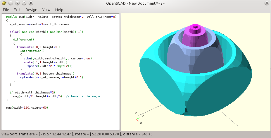 |
| A recursive mug. Make sure you have a version of Openscad that allows this (an indicator is that the syntax is now colored: another long-waited feature!) |
module mug(width, height, bottom_thickness=2, wall_thickness=5)
{
r_of_inside=width/2-wall_thickness;
echo(width); // print the value in the console
echo(width); // print the value in the console
color([abs(cos(width)),abs(sin(width)),1]) // color with size
{
difference()
{
translate([0,0,height/2])
intersection()
{
cube([width,width,height], center=true);
scale([1,1,height/width])
sphere(width/2 * sqrt(2));
}
translate([0,0,bottom_thickness])
cylinder(r=r_of_inside,h=height+0.1);
}
}
// At this stage we are back to the default union() behavior
// At this stage we are back to the default union() behavior
if(width > wall_thickness*2) // only is there is room
mug(width/2, height+width/5); // add a smaller mug here
}
If you still get only one mug, check the console for an error like "WARNING: Ignoring recursive module instanciation of 'difference'.". This would tell that your version of Openscad does not support recursion and that you should probably upgrade. In the "Help / About" menu, check that the version is more recent than the 2014.01.29 (e.g. the 2014.04.02 as above).
Also the generated sizes are now harder to track, so we used the echo command to show how to get the value of width each time the module is called:
echo(width);
After you refresh the design, the console dumps the following:
ECHO: 100
ECHO: 50
ECHO: 25
ECHO: 12.5
ECHO: 6.25
Important note: the very weird properties of variables in Openscad will not be discussed here. Even though recursion was recently allowed and not discussed in the following document, I highly suggest reading this detailed presentation of variables when you need it, written by +Stephanie Shaltes. By the way, she regularly posts about advanced subjects in Openscad so she may be interesting to follow on G+.
Advanced concepts
The minkowski operator is quite cool. But it is so slow that we almost never use it. The effect is like when a shape is used to paint or "brush" a parent shape: e.g. a small sphere will "round" all the edges and surfaces of a given reference object.Shown below is an example where we use only 2D shapes, that Openscad also supports (we then use square in place of cube, circle for spheres and so).
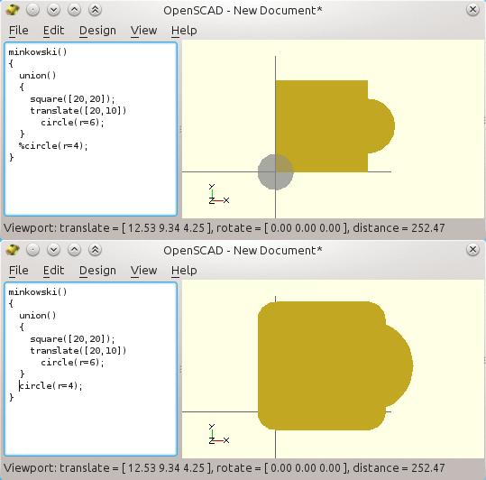 |
| The minkowski operator, illustrated here on 2D Openscad shapes. It does works in 3D also but is so slow that the shape is usually better designed otherwise. |
More importantly, there are also two kinds of extrusions, linear and circular, that makes 3D shapes out of 2D shapes.
They are very useful to create 3D shapes out of "industrial" 2D designs (often based on the Autocad DXF file format that Openscad knows how to import).
Here we will "raise" our former 2D shape vertically and make it a 3D shape, here is what we write:
linear_extrude(height=30)
{
minkowski()
{
union()
{
square([20,20]);
translate([20,10]) circle(r=6);
}
circle(r=4);
}
}
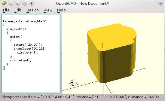 |
| 3D linear extrusion of the former 2D shape |
Contrary to the linear extrusion, the rotate_extrude( ) operator can be used to create a "ring" out of a 2D profile. This is how we extrude a rough circle into a torus (note how the circle must be translated out of the origin to do so!).
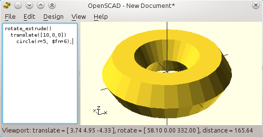 |
| Rotational extrusion of a basic 2D hexagon (a 6-segment circle) |
One annoying thing with the "rotate_extrude( )" is that it does make partial rotation. It will always "close the loop".
So when you need only 1/4th of a turn (i.e. a partial 90° rotation), say, then the best way is to intersect the shape with a cube, like this:
 |
| Easy 90° slice of the torus, with an intersection of the former torus and a big cube that stands in the positive (X,Y,Z) spatial quadrant. |
Now, for any angles smaller than 90°, we can create a "wedge" shape by means of a convex hull around two very thin slices (almost flat cuboids), where one of them is rotated by the expected angle (see, by the way how modules can be defined within modules).
 |
| A 45° "slice" of the initial torus, but it works only with for small wedges. |
You may have seen the use of the weird expression (center==true ? -height/2 : 0). This is a compact form of a conditional, usually barely readable: "if center is true, then replace the expression by the value -height/2 else use the value 0". This is a short way to code a condition, which is used here to shift the part downwards by half the height in order to center it, like it is done with cylinders.
We did not use a more usual "if" test, as in the recursive mug. It would make life harder as "if" works with shapes, and not operators: the "if" condition cannot apply on the presence of the "translate" operation itself, but only on whole shapes. The "?" shorter version applies only on mathematical expressions, suitable here. All in all, in some case we will ask for a translation of (0,0,0), which works!
Anyhow. The above wedge design fails when the angle is larger than 90°, as the hull will flatten the two-wall wedge (see the animation below).
 |
| A convex hull between the first and last "wall" fails with any large angles! We will see Openscad animation later. |
To create a pseudo-wedge that really can span 360°, we can use a succession of hulls no bigger than 45°, and that are progressively rotated around the Z axis.
So using a loop is very natural to generate the intermediate walls, spaced here at 45° of each other.
Still, we need to add the last wall "manually" as it may not fall on a multiple of 45° as below.
 |
| Angularly-spaced thin wall to help building the required concave wedge. |
module wedge(angle, extent=100, height=100, center=true)
{
module wedge_wall()
{
translate([0,0,(center==true ? -height/2 : 0)])
cube([extent,0.1,height]);
}
for(r=[0:45:angle-1])
rotate([0,0,r])
wedge_wall();
rotate([0,0,angle])
wedge_wall();
}
wedge(angle=200);
Now, we want a shell somehow like a hull around this skeleton...
But a regular hull( ) around the thin walls would fail badly, as it would "fill" also straight from the first wall to the last wall. The required concavity made by the first and last walls would not be respected. Sure, as the operator builds a convex hull. A concave hull probably has no meaning anyway, we must build it by hand.
So what's the trick? The expected concave wedge shape can be made by unions of successive hulls!
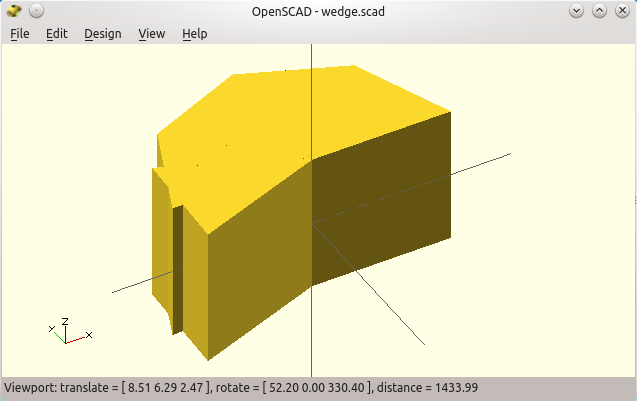 |
| Here is our first attempt at a potential "concave" wedge. It works but it makes a dirty source code (so far). |
module wedge(angle, extent=100, height=100, center=true)
{
module wedge_wall()
{
translate([0,0,(center==true ? -height/2 : 0)])
cube([extent,0.1,height]);
}
for(r=[0:45:angle-45-1])
{
hull()
{
rotate([0,0,r]) wedge_wall();
rotate([0,0,min(angle,r+45)]) wedge_wall();
}
}
hull()
{
rotate([0,0,max(0,angle-45)]) wedge_wall();
rotate([0,0,angle]) wedge_wall();
}
}
wedge(angle=200);
The min and max are required to avoid overshooting the expected wedge angle.
Here are the result of the intersection of our wedge and the initial torus, that finally does it.
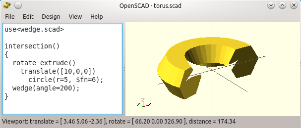 |
| It works! The parametric wedge "sliced" the torus the way we wanted. Note the "missing" part? It is only a rendering issue, see below! |
 |
| Here is why there is a "convexity" parameter in the rotate_extrude(), and a few other Openscad functions. It helps the renderer by telling to look deeper in the intersection of objects. |
Well... OK, it works... but the source code got much polluted...
It can get cleaner with the beautiful and somehow forgotten / unusual concept of children in Openscad. And that will make yet another part in this introduction to Openscad (to come!)